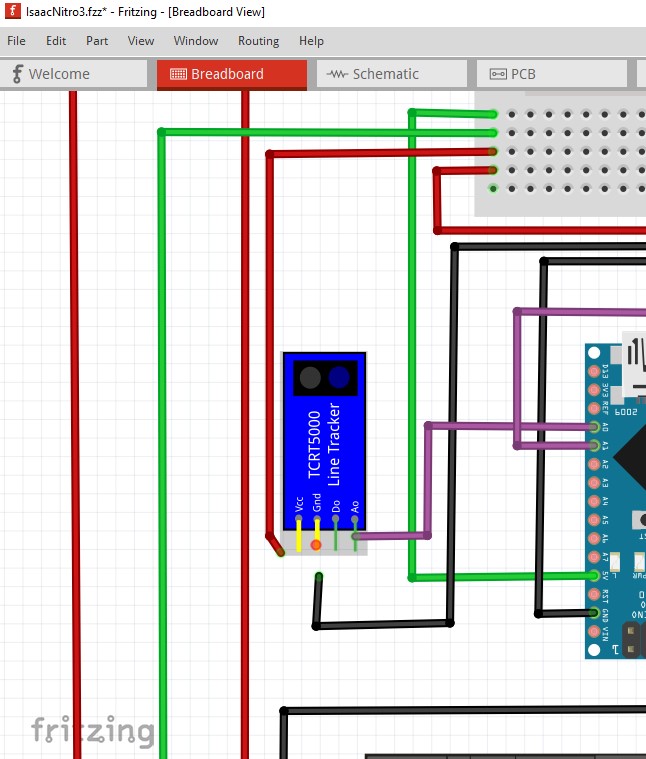
Basically, I’m creating a line follower car for an university assignment. I already mounted the car, connected all the wires and am only waiting to finish the code to test it. The problem is, I need to create a schematic based on the project and the Fritzing autoroute keeps making updates (seemingly) different from the circuits connections I made. When I try to fix the schematic, it updates my protoboard project against my will. I’m uploading the .fzz file so anone can help me and show me any possible mistakes I may have committed. Thanks in advance.
IsaacNitro3.fzz (124.4 KB)
You have a broken part. The TCRT5000 line tracker part has a short from power to ground and another from DO to AO.
I’ll post a corrected version in a bit. Here I clicked on a pin on the TCRT5000 (after disconnecting the wires) and it lights up both power and ground indicating a short between the two (probably an incorrect bus definition.)
edit: there is more wrong than just the part. You have a short power to ground in pcb and another somewhere else in pcb or schematic. Here you see the nano ground pin is connected to the 5V pin a couple up from it causing a short (which reflects in to schematic and pcb.)
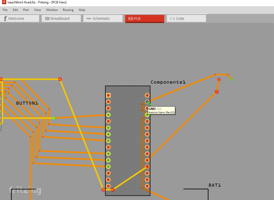
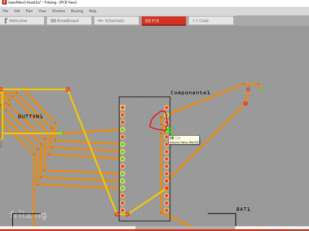
here I clicked on the 5V pin (which is connected to GND!)
That still didn’t clear the short so I deleted all traces in pcb and schematic then installed this new (fixed) part in breadboard
TCRT5000-Line-Tracker-fixed.fzpz (5.1 KB)
This new part is in and connected in this sketch
IsaacNitro3-fixed.fzz (80.9 KB)
although as noted schematic and pcb are currently unrouted. Your best bet is to click in a rats nest line in schematic then manually route the resulting wire, then do the same in pcb. The rats nest lines make the correct connections. You should also check breadboard to make sure I didn’t screw anything up ![]() .
.
Peter
1 Like
Thank you! I appreciate the tips and the fixed files very much!