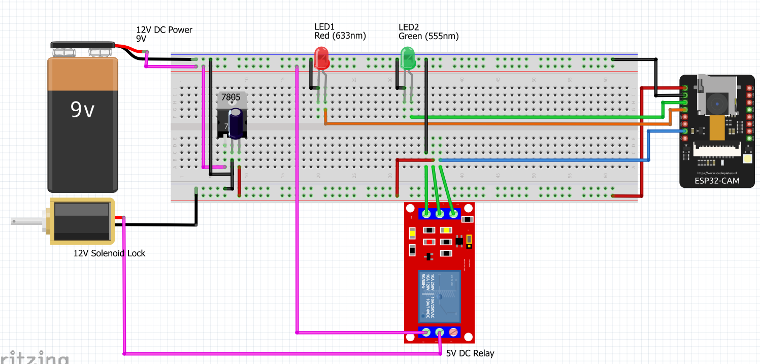
I’m trying to build a face recognizing door lock from a youtube tutorial, but the circuit is totally broken, Need some help fixing it.
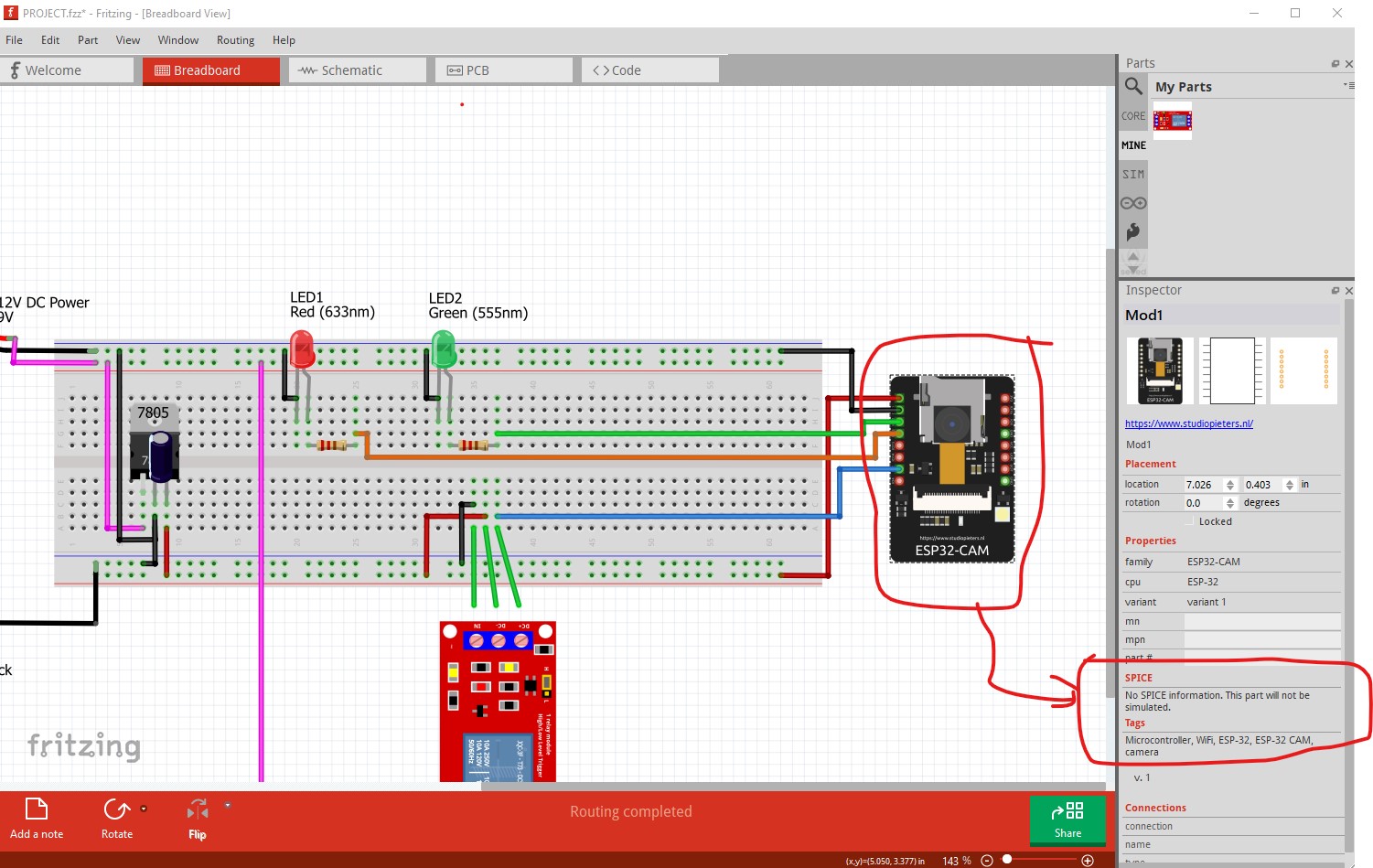
To say anything useful we would need you to upload the sketch (the .fzz file, upload is 7th icon from the left in the reply menu) and tell us what problem you are having. This circuit is unlikely to simulate as several of the parts likely won’t have spice models (camera, relay and solenoid.)
Peter
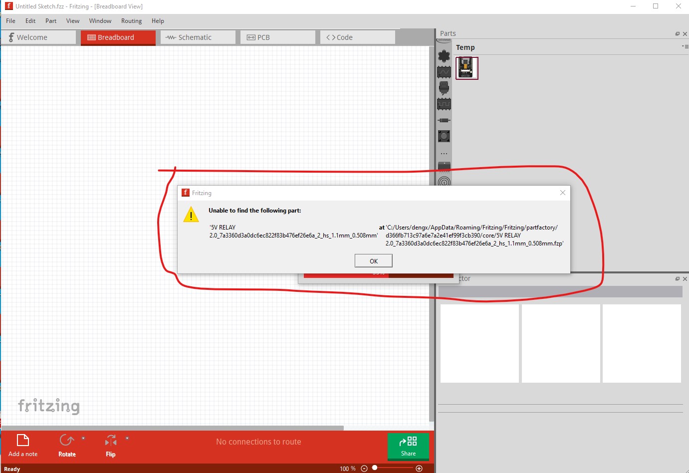
The .fzz file doesn’t load for me. That is likely because the 5V relay part is incorrect. If you post the .fzpz file for the 5V relay part I will have a look at correcting it.
As well you didn’t specify what the sketch doesn’t do other than simulate (which as noted is likely due to no spice models.)
edit here is what your sketch looks like here
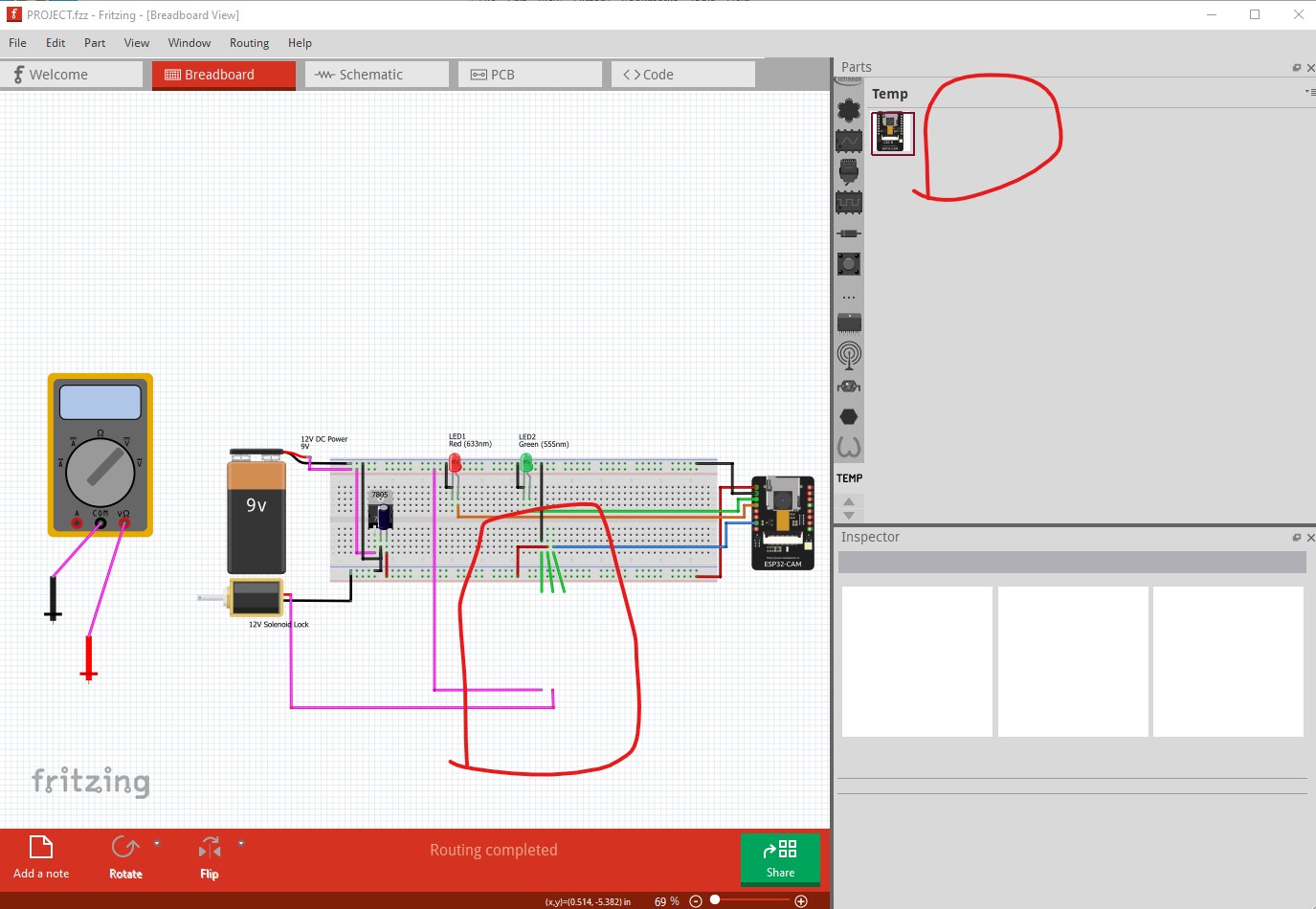
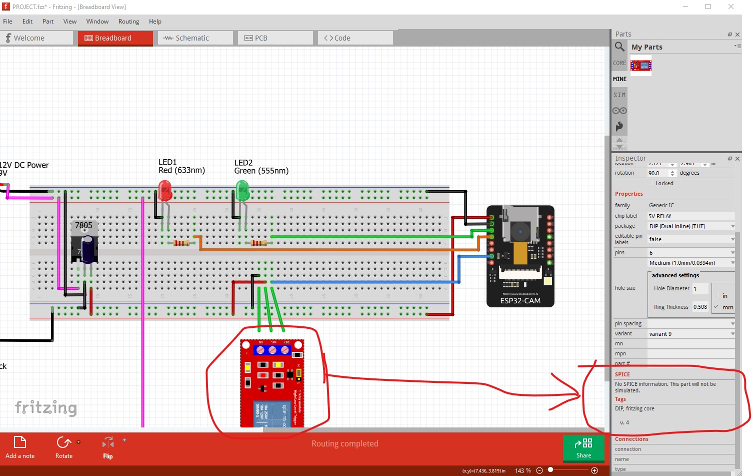
the 5V relay part should appear in the temp parts bin (this is a reported Fritzing bug.)
Peter
5V RELAY 2.0.fzpz (16.3 KB)
I got this relay from other topics found in the forum.
um new to this software, ![]() donno what a spice model is, sorry.
donno what a spice model is, sorry.
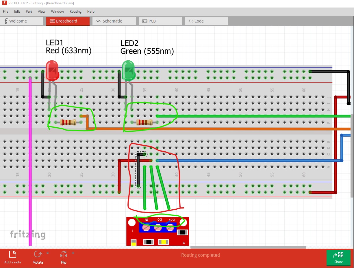
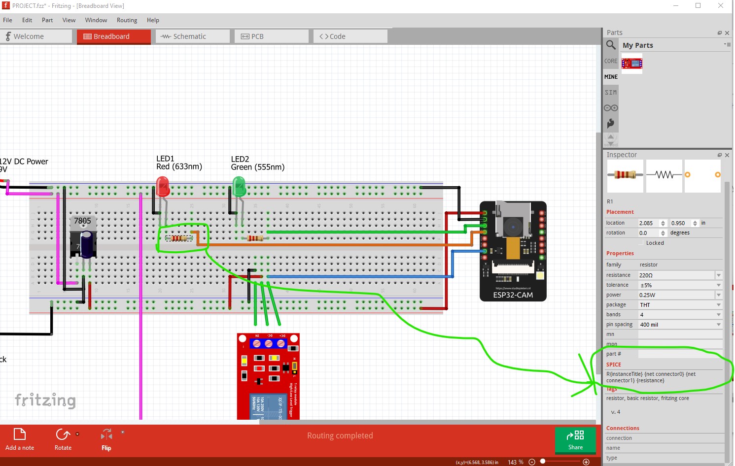
There are more problems here than I can deal with tonight. I have fixed the broken part but replacing it in your sketch still breaks (although in a new way now.) The new part (where I adjusted the font sizes so the labels are readable) indicates your breadboard wiring is wrong. The labels are circled in green. The corresponding wires circled in red are incorrect. Ground is going to “in”, “+5V” is going to ground on the relay and “5V” is going to ground. That needs correcting. As well the LEDs need current limiting resistors (also circled in green here.) As it is wired the IO ports on the camera are likely to be damaged by drawing too much current though the LEDs because of no current limiting resistor.
As well there is no spice data (spice is an analog simulator which needs spice data in the part which many parts don’t have and in the case of CPUs like the camera isn’t practical to create) so unless the part has spice data it can’t be simulated so most of this circuit can’t be simulated.
the resistors have spice models so they can be simulated.
Here is the part for the relay. You may have to start the sketch from scratch using this part to make it work properly as replacing the part in the current sketch hasn’t worked for me (although it should, indicating there are more bugs!)
5V RELAY 2.0-fixed.fzpz (15.1 KB)
Peter
1 Like
OK I have figured out what my problem is (the corrected part is still badly configured.) This new part fixes the issue and I will report it as a bug although I don’t see how we can fix it.
5V RELAY 2.0-fixed-better.fzpz (15.1 KB)
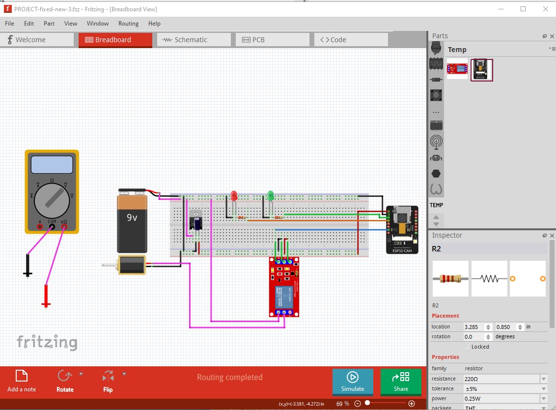
This part is in this sketch which I think implements what you want correctly (but still won’t simulate!)
PROJECT-fixed-new-3.fzz (97.4 KB)
The sketch looks like this
breadboard
schematic
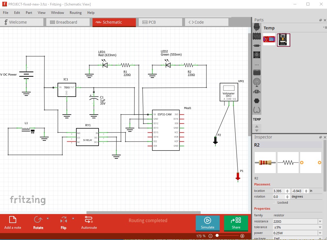
loading PROJECT-fixed-new-3.fzz should give you the same output.
Peter
1 Like