MPU-6050_IC.fzpz (10.1 KB)
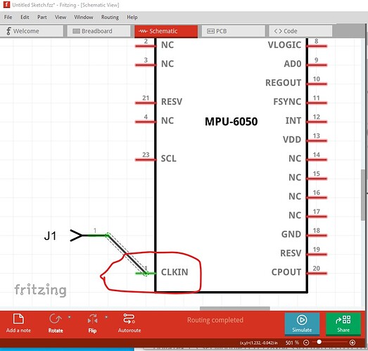
Your part has a number of problems (many of which may not affect operation though.) The main one is that schematic lacks terminalIds which causes the part to be misaligned to the grid and the wire to connect in the middle of the pin like this:
Note that the center of the pin is aligned to the grid rather than the end (the terminalId will correct that though.) I ran your part through FritzingCheckPart.py which has a number of complaints (which as noted may not affect operation)
Warning 13: File
‘part.MPU-6050_8d9554233d8b90d4f00213564321f43b_2.fzp.bak’
At line 58
Value connector2terminal doesn’t match Id connector5. (Typo?)
This indicates the terminalId set (but not used because it isn’t in the svg file) in the fzp file doesn’t match the connector name. As well a number of the pin ids (which are used) don’t match the connector name
Warning 13: File
‘part.MPU-6050_8d9554233d8b90d4f00213564321f43b_2.fzp.bak’
At line 254
Value connector9pin doesn’t match Id connector12. (Typo?)
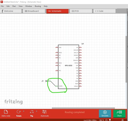
as long as the svg uses connector9pin as the connector name this will work fine, but it is annoying when trying to modify the part. Here is a corrected version of the part (I removed the buses and the EP pin which this chip doesn’t appear to need) and upgraded it to meet the graphics standards (mostly sizes and colors.) Now the pins align to the grid and the wire connects to the end of the pin rather than the middle.
MPU-6050_IC.fzpz (8.8 KB)
this part has the same moduleId as the original, so you would need to delete the original before being able to load this one.
Peter

