Can anyone fix the pin spacing of the part named SWITCH-MOMENTARY-2? Here’s an image of the correct spacing compared to the original:
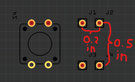
Also, the part only has 2 pins, it should have 4.
Can anyone fix the pin spacing of the part named SWITCH-MOMENTARY-2? Here’s an image of the correct spacing compared to the original:
Also, the part only has 2 pins, it should have 4.
I’m not seeing a problem on the spacing. The switch appears to be 0.2in by 0.5in from both the grid lines and the ruler in pcb view. It does appear the part is missing the buses that tie the pins together but that makes no practical difference as the pins are connected together internally. It is easy enough to make a new part though. It may also be an idea to check the Sparkfun Fritzing repo to see if there is an updated Fitzing part there (Sparkfun maintains their own repo.)
Peter
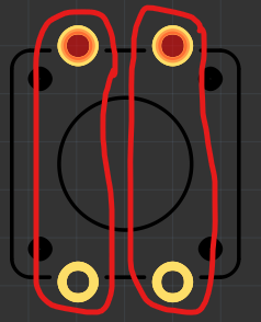
The spacing is wrong by a little bit, look what happens when I copy the part and flip it:

Also I know having only 2 pins is fine but I want it to have the 4 pins for when I make my PCB design, I want to use all the 4 pins.
I expect the offset is placement of the silkscreen not being symmetrical. To do this I need to know which pins are connected together. It isn’t obvious from the original switch (as two pins are unconnected.) So is the switch between the two 0.5in pins or the two 0.2in pins?
Peter
This is how the pins are connected:
This should do what you asked for. I’d check the hole size before ordering boards, it is 0.047in which seems fairly large (a 0.1 header is 0.038in) but is same as the original.
SWITCH-MOMENTARY-3.fzpz (5.0 KB)
Peter
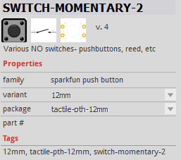
Can someone help fix the pin spacing for the part named SWITCH-MOMENTARY-2? The current version doesn’t match the correct layout. I’ve attached an image showing the right spacing: the vertical distance between the top and bottom pins should be 0.5 inches, and the horizontal spacing between pins in each row should be 0.2 inches. Also, the part is only showing 2 pins, but it should actually have 4. Thanks in advance!
No image got included with your post. Is the referenced part broken, or do you just have a different part? There are a lot of possible footprints for push button switches.