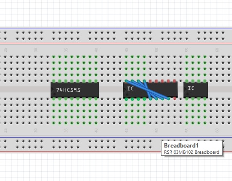
With the latest version, 0.9.3b, I put a generic IC on the breadboard and the then go to Inspector->Pins and change the default 8 to 16. However, the result sounds messy! Please look at the picture and you will see some wire exchanges and also the green dots (to show connected holes) are not present. What does that mean? Did I miss some steps to enlarge a generic IC (from 8 to 16)?