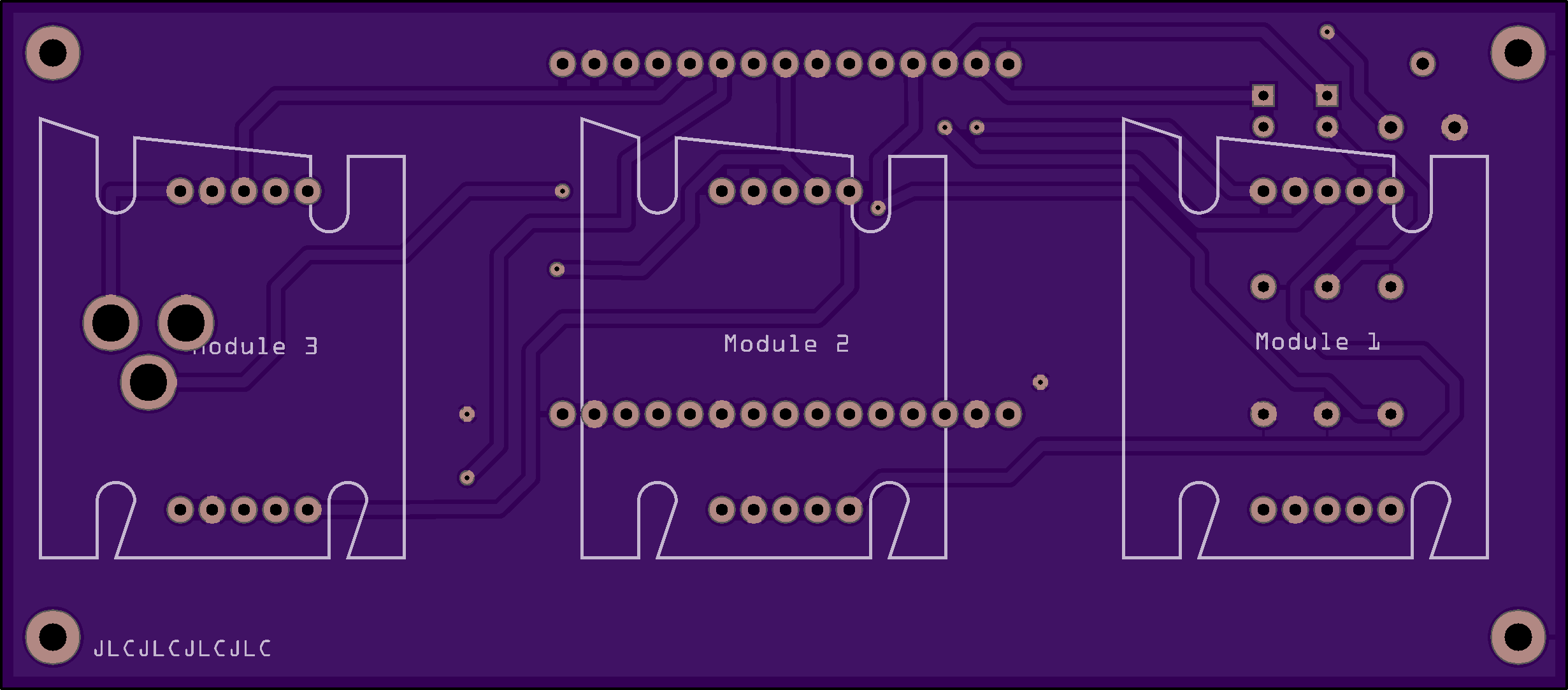
My module spans a whole breadboard vertically with a one row gap. I don’t know how to describe it better but here’s a picture (red squares would be the pins)
edit: Correct the part! The SDI and SDO pins are separate not bused together like the other 4. So remove the SDI/SDI bus and rename the output pin SDO.
edit1: Hopefully third time lucky, missed changing the pin label in the .fzp file from SDI-out to SDO-out. Corrected in this part.
wow, this is perfect, thank you so much! You even caught the incorrect pin order which for some reason I missed. You just saved me from having to throw away 5 PCBs (or mess around with flying wires). And it also looks like a 8x8 LED matrix now.
I actually think this is the most common size. I compared it to an old 2*5 pin I2C matrix I have lying around and it has the same pin spacing and dimensions.
The only thing I would change is the naming of the SDI/SDO pins. You named SDO as SDI Out but SD stands for Serial Data so it’s Serial Data In (SDI) and Serial Data Out (SDO).
In the schematic they’re also both labeled SDI. Note that internally they are not actually connected directly! The order of SDI to SDO matters if you are chaining these modules.
I would have changed it myself but I see that it’s in the SVG files and I have nothing to edit them.
You are right, old eyes. I missed that only the other 4 pins are connected together not SDI/SDO in the schematic. It should have been obvious when I needed to add a bus entry for the SDI pins but it wasn’t. It would also be a good bet to make sure the pins are in the correct order looking down from the top because I had to mentally rotate the bottom of the board image on the web site by 90 degrees then invert it to get to the top of the board and I may not have done it right (although I think it is!) I have replaced the part above with a corrected one. You will need to delete the part in your mine parts bin then restart Fritzing to get it to really be deleted.
The usual answer is Inkscape (which is open source) but it is fairly complex to use. Various of the commercial packages (Illustrator, Coral Draw others for the Mac) work as well but Inkscape is the most familiar one usually. As well in this case you would need to change the bus configuration (internal connections in the parts editor) to remove the link I added from SDI to SDO. Someone in a recent thread has found an online svg editor, but it seems to be like Illustrator and shield you from some of the important parts (such as dimensioning the drawing in px which causes scaling issues in Fritzing. ) Inkscape used to be poorly supported on the Mac (I think for a while they didn’t publish Mac versions) but I think that may have changed now with the latest version, but I’m not a Mac user.
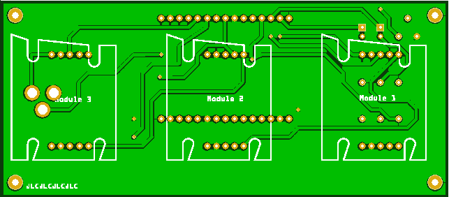
At the last moment, I noticed another strange thing. The silkscreen in the exported Gerber files of the part are weirdly distorted. Aisler uses the .fzz file instead, which doesn’t have any issues.
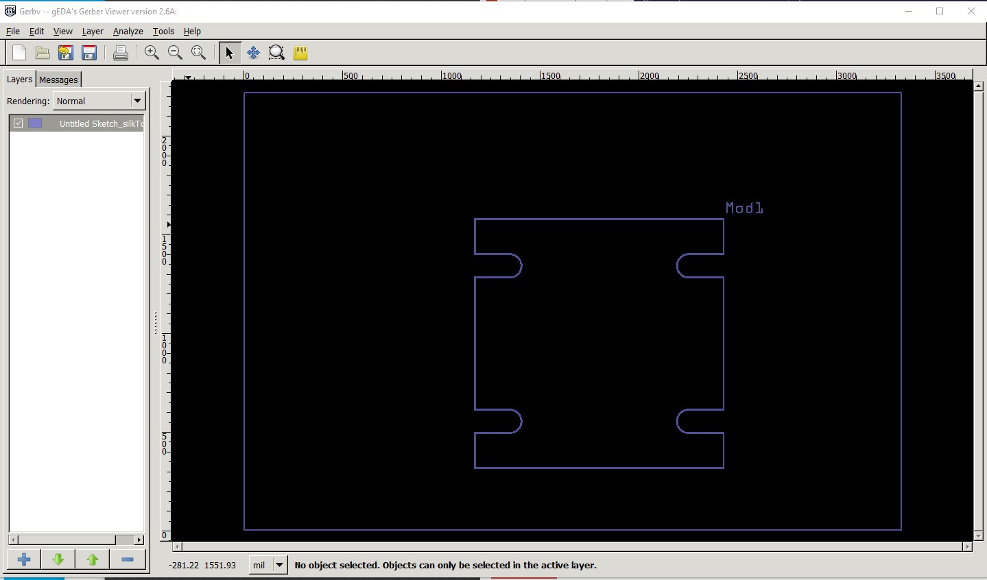
Which Fritzing version are you using? This looks like a bug in 0.9.3b and 0.9.4 with paths. On 0.9.6 on Win10 the silk looks to render correctly in the gerber output:
We are all hoping that , the voluntary donation rate was something like 0.1% of downloads. While the paywall is very unpopular, it is necessary if Fritzing is to survive. The way forward is thought to be paid professional developers, the code base is too complex for volunteers. I tried to restart development for about 3 years with 0 success. Lots of people arguing for a fork of the code base, but none willing or able to actually produce pull requests on the current code base, where the maintainers said they would merge valid pull requests, there just weren’t any. The paywall (and Aisler, whose CTO drove the push that got 0.9.4 released!) have produced (mostly invisible) updates to the web site, forum and build chain (all a huge amount of work!) and the 0.9.4 and 0.9.6 releases at a time when Fritzing was starting to die from outdated libraries.
I can see that this would make sense. Being a developer myself (well now more operations, but still) and having worked with large code bases, I can imagine that this isn’t something you could maintain with only volunteers. 0.1% donation rate also doesn’t really shock me.
It’s a great tool for the occasional DIY PCB that I do. I’m not an electrical engineer but I made a large 35x35cm PCB with Eagle once and that gave me a fair share of gray hair.
That and breadboard view (which is unique AFAIK in open source at least) are Fritzing’s strengths. It is relatively easy to use (although parts making is not) and is the only open source package I know of that will allow you to document the connection of a series of modules (as long as there are parts for them) which is mostly what I do these days rather than make boards. It is very popular in the maker community (around 200,000 users from github parts update statistics I believe.) Unfortunately the developer class folks find it too limiting and move on to kicad, Eagle or one of the commercial offerings.
It makes sense. Eagle etc. are of course more geared towards the professional market.
But you’re right, Fritzing is perfect for the maker community or for teaching kids. Personally I’ve never used the integrated code editor but for small and simple projects it makes perfect sense to have everything integrated in one package where you can see your breadboard view, the schematic and the code. The PCB view is just an addon then and most likely won’t be used by too many people from this group.
I really like Frtzing, which is why I keep coming back to it
And the community here seems to be awesome and helpful too!