Here are a few more improvements. It would be a good thing to offer the corrections back to the original author of the part (assuming they are still around, since the part seems to be from 2014.) If this is from the Sparkfun repository a pull request there would be in order.
LIDARLite-Fritzing-Part-improved-more.fzpz (7.8 KB)
this is a new part (different moduleId, family and file names) so it will load along side the other parts.
Changes:
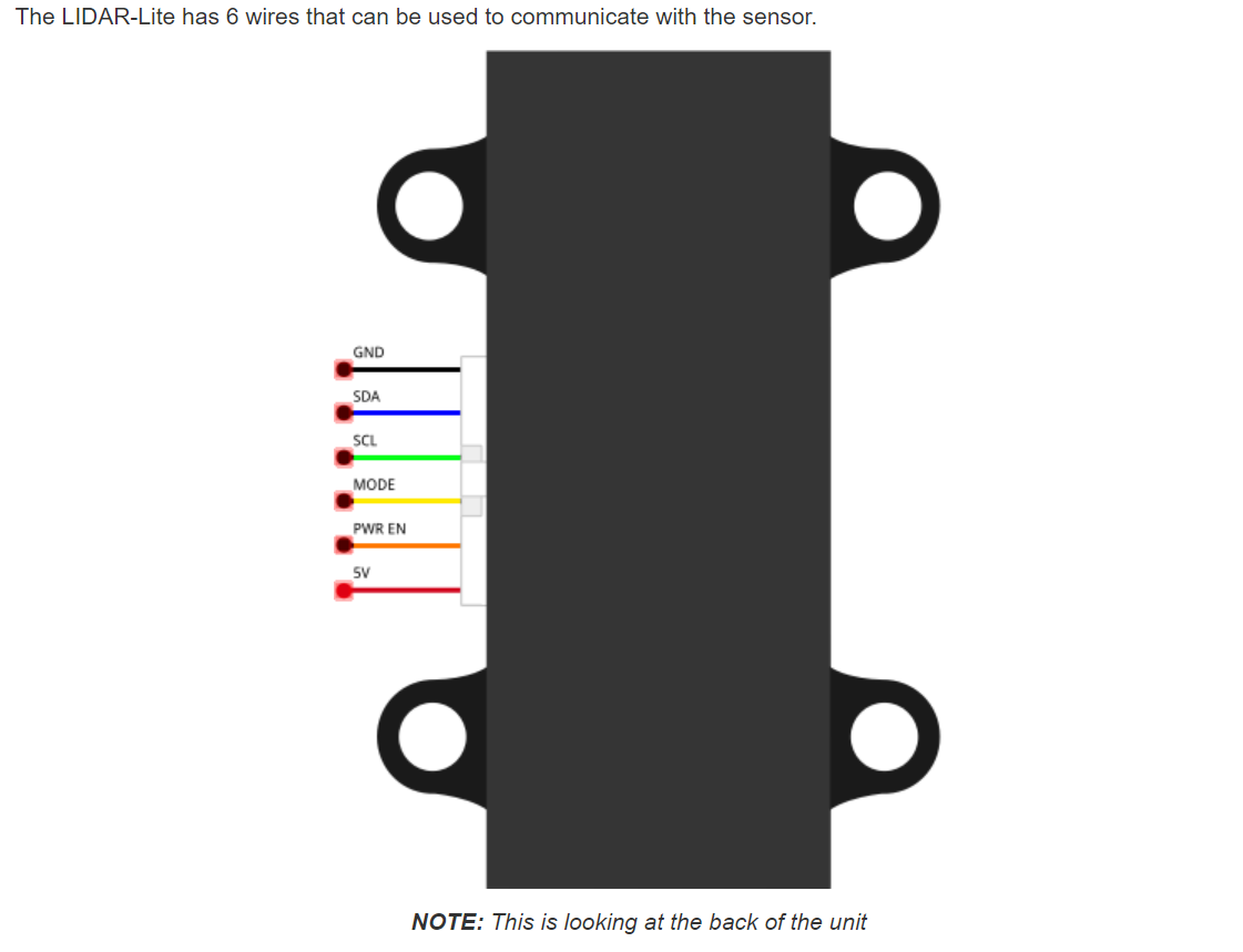
Breadboard
Rescale the svg to the standard. Change dimensions from px to in (as px can cause scaling problems) then rescale slightly to get the pins back on .1in boundaries, otherwise no changes (I didn’t change the wire colors either.)
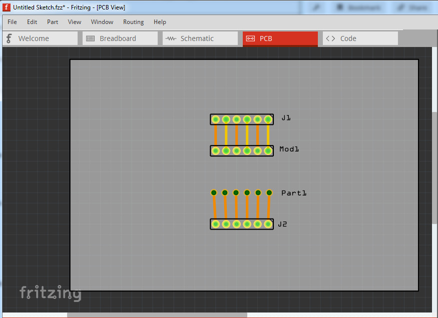
pcb
Replaced it with a copy of a 6 pin header. The current pcb is misconfigured so it will only route on the bottom of the board and the pins are all ellipses and will not generate a hole in pcb, they are also not on .1in boundaries (top is the new part bottom the old here.)
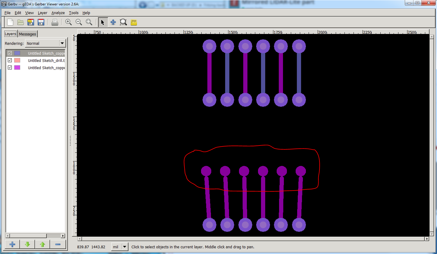
and the gerber output
Note the original part (circled in red) has no holes (the pale circle in the other connections), isn’t on .1 boundaries and the traces aren’t connecting to the pads correctly
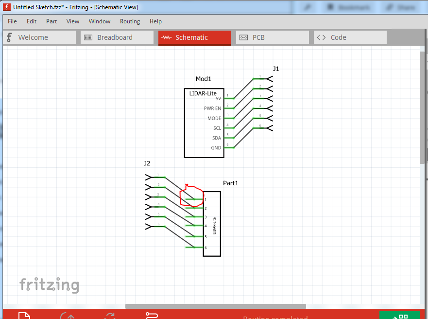
Schematic
Replaced completely with a standard template. Changed the pins to exit on the right (for convention inputs on the left of a schematic, outputs on the right.) Add pin label names as well as pin numbers. Insured the terminalIds were set so the wires terminate on the end of the pin as they should (the original looks to have no terminalIds defined and thus terminates in the center of the pin.)
fzp
change moduleId add Fritzing version
added Mod to label (to change Part1 to Mod1)
changed family to LIDAR-Lite (sensor is likely a conflict)
changed file names to make this a new part with new moduleId and family
renumbered connectors to be sequential
remove unused terminalId for all breadboard definitions.
added missing schematic terminalId to pins 4 and 5
Peter
 .)
.)