 MicroSD_Badusb.fzpz (66.2 KB)
Your part has a number of errors (some of which I have corrected) but I’m stopped at pcb. I assume the pads are on .1 centers but your current pcb is not. I can’t see any data for this particular board in a google search so if you can supply a pointer to a a mechanical drawing that shows the pin layout and spacing I can fix up the pcb view as well.
edit: drawing not needed. Once I stopped ignoring the warning message that the view box was defined in px which can (and was!) cause scaling problems. I was able to fix up the part (it was created on Inkscape at 90 dpi and I was editing on an Inkscape using 96 bpi). This version was created as a new part so you can load it along side yours and see the changes I have made:
fpz:
change type=female to type=male
add copper0 to pcb layer definitions
added busses for the bused pins
Breadboard:
ungrouped everything to clear unneeded groups
added layerId breadboard.
rescaled to in from px (scaling problem)
Schematic:
corrected size from px to in and adjusted scale
added schematic layerId
added terminals for all the pins.
Aligned on .1 in centers as they should be and reduced size of schematic.
pcb:
corrected size from px to in
added group copper0 which was missing
changed hole size from .040 to .038 (.1 header size).
MicroSD_Badusb_fixed.fzpz (32.4 KB)
This may be an interesting board. Do you know if you can program it? It sounds like the answer is no (“no foundation no refund” (which I take to mean no bootloader so you can’t load new code in to it). I think as much as you can do is load scripts in to it to use on USB which isn’t interesting but I’d like to be wrong 
Peter
Many thanks Peter.
sorry, but that is my first deposit at Fritzing forum.
Agree your correcteds.
Only one week recept this module. connected at PC there is real Arduino Leonardo, with led blink pin13 program.
My first work is digital pins numbers for programing:
for this, i used the Arduino ide with Leonardo module, Exemples/Basics/Blink program.
digital results are:
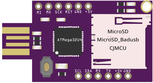
MISO pin14, MOSI pin16, SCK pin15, SCL pin3, SDA pin2, RX pin0, TX pin1.
the 2 leds at left side of SD card are pin13 & pin8.
added it in MicroSD_Badusb_fixed, at the connectors section.
changed the pointer of first pin of ATmega, in breadboard vue.
My first project is GPS walker, the pet cat collar register, the environ home cat is 1Km !
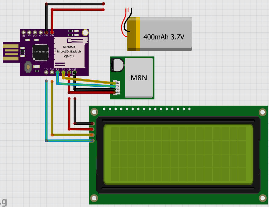
the LCD is for debugging, battery is for autonomous usage.
for telemetry i dont use TinyGPS library, but youtube/iforce2 UBX NAV_PVT message system.
veille is in minutes.
for CPU veille use the Gammon. http://www.gammon.com.au/power (n * 8 secondes)
for GPS veille use UBX RXM_PMREQ message for UBX8 protol.15(2.6mA) or command pin with UBX7 protocol.14(75yA).
the must result is: ATmega328P at 8Mhz(no quartz) with UBX7 command pin.
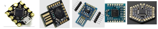
This week i recept 2 Wemos ATMega32U4 BS Micro Pro Leonardo, usb male & female.
expected CJMCU Beetle Controller coin, usb male & female, but is out of stock.
expected DFROBOT yHex Low Power Controller(ATmega328P).
visit the cjmcu.com chinese site, but dont have the datasheet ! the problem is for pins MOSI/MISO/SCK reused by SD reader ?
The problem with this module: is replicant of Rubber Ducky. with max memory and hacker program, permit download entire PC machine.
this new CPUs are history, are great revolution, i enjoy to be participed !
Fell Maurice
Over all a good job for a first part. Most of the problems are fairly minor and some of them were probably caused by the part you cloned from (not all the parts in the library are correct!)
That’s good to know, as it may be useful in some cases as it looks to be smaller than the nano and has the sd card. I may buy one the next time I’m doing an order.
Yes I looked at them, there isn’t much data about it anywhere I can find. The MOSI/MISO/SCK are indeed usually shared, there is usually (but not always, and perhaps not implemented here if they didn’t intend to share more than the SD card) a CS pin that can select and deselect the SD card so you can put more than one thing in the SPI bus. You may have to trace the leads on the board to the SD socket to see if one of the pins can deselect the SD card so you can select something else on the SPI bus.
Peter
Hello,
Do you know if that is possible to use ds18b20 temperature sensor with this board please ?
Thanks