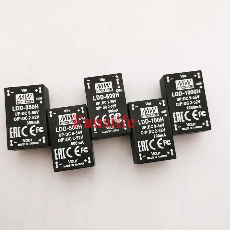
LDD-300~1000H
hi i was looking first in google in the forum, no results
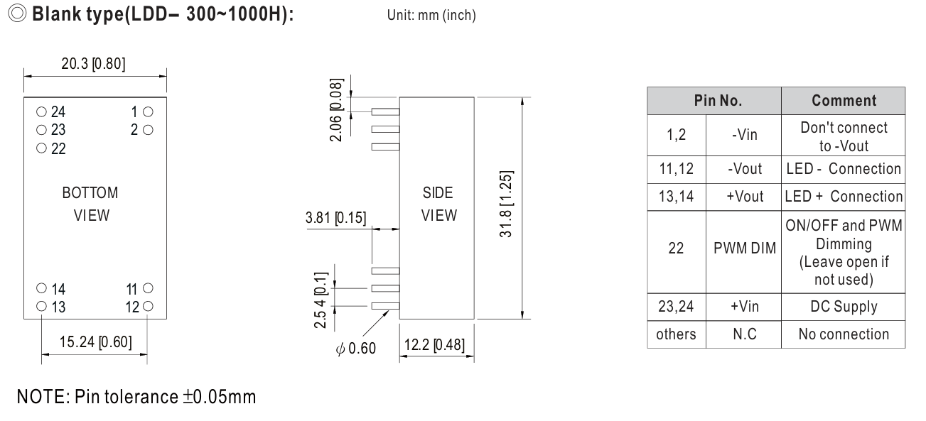
Datasheet
im looking for: Blank type (LDD-300~1000H)
LED driver
LDD-300~1000H
hi i was looking first in google in the forum, no results
Datasheet
im looking for: Blank type (LDD-300~1000H)
LED driver
Which exact size are you looking for? While the only thing that seems to effect (in Fritzng terms) is the label on the part (the pin spacing is identical) it is likely preferable to get that correct.
these seem to be the choices.
Peter
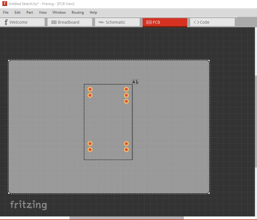
This part should do what you want. The pcb hole size is 0.038in which will take either a 0.1in header or the pin from the power supply if you want to solder them in.
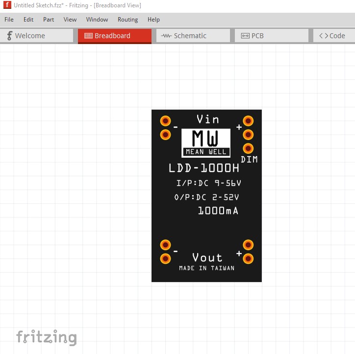
edit: replace the part with one set to 1000Ma in breadboard to match the one you have.
edit (4 July 2024: replace the part with a corrected one, the DIM pin was 0.1 too low!)
edit1 (5 july 2024) there was a second error in that the bottom 2 pins are 0-.1in too high. Move them to the correct position.
LDD-300-1000H.fzpz (4.5 KB)
Peter
yes i was looking for the LDD-1000H model
thanks… i will test my pcb
The best bet would be to print out the pcb footprint at 1:1 scale and compare it to a real part (as I don’t have one!) I think it should be correct but checking before ordering boards is the best bet. I replaced the current part with a new one that is labeled as the 1000Ma version as well.
Peter
yes i will notify if need the scale when i got my LDD part
thanks again
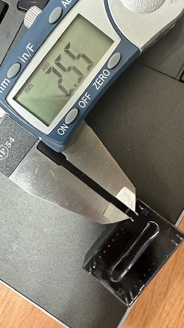
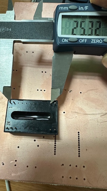
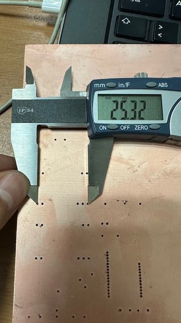
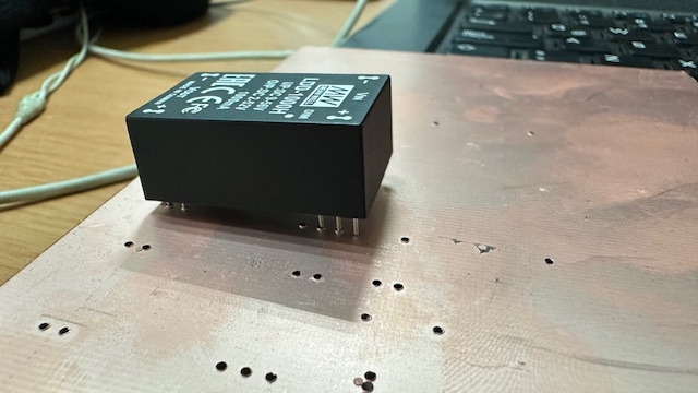
hi, i just recieve them… i think the footprint can be improve, would you help me to correct it? thanks in advance
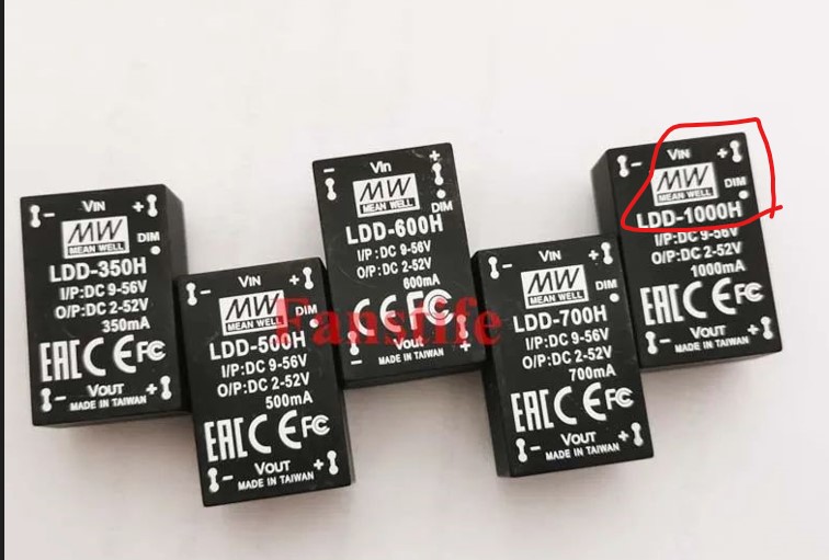
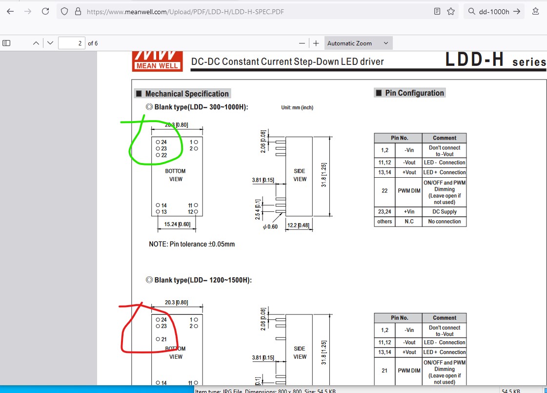
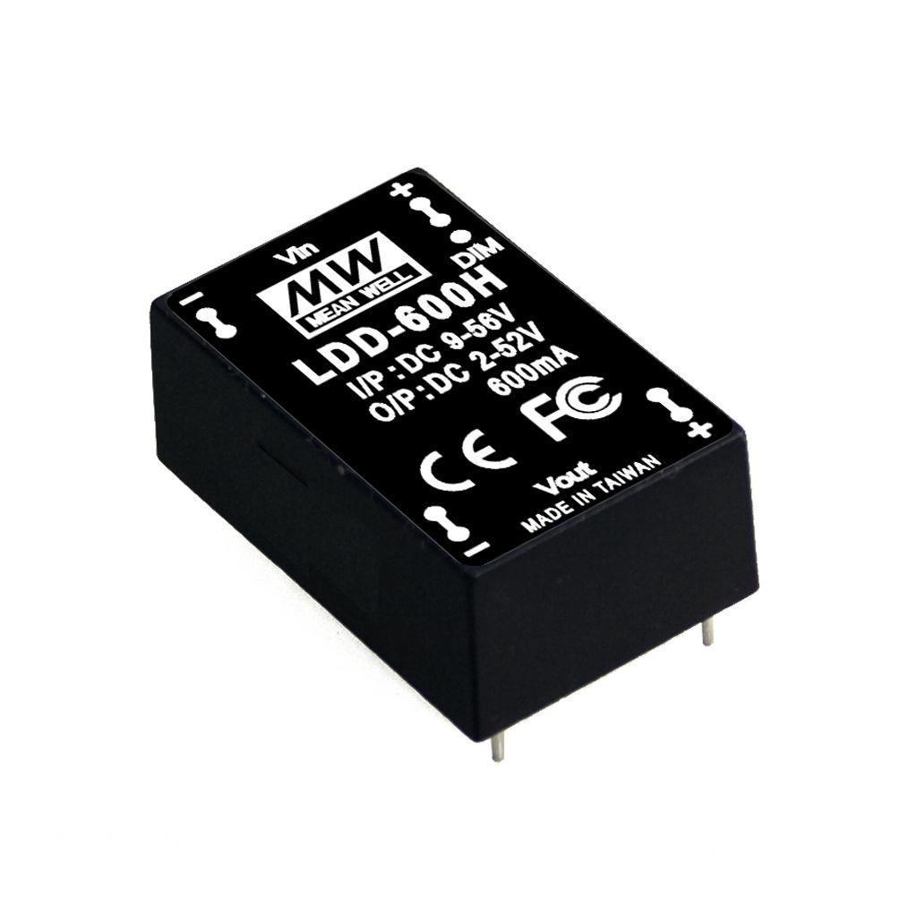
Looks like I screwed up and believed this jpg image
which doesn’t match what the data sheet says for the 1000H only the 1200H and 1500H
and I used those measurements. I have corrected the part and will replace it in a minute. You will need to delete the current part from your mine parts bin then shutdown Fritzing and restart it (to complete the deletion, answering yes to the save the part prompts.) Then reload the new part. Which looks like this and I think should be correct:
(the DIM pin moved up 0.1in in all views to match the datasheet!)
Peter
thanks i will try now with the pcb thanks again!!
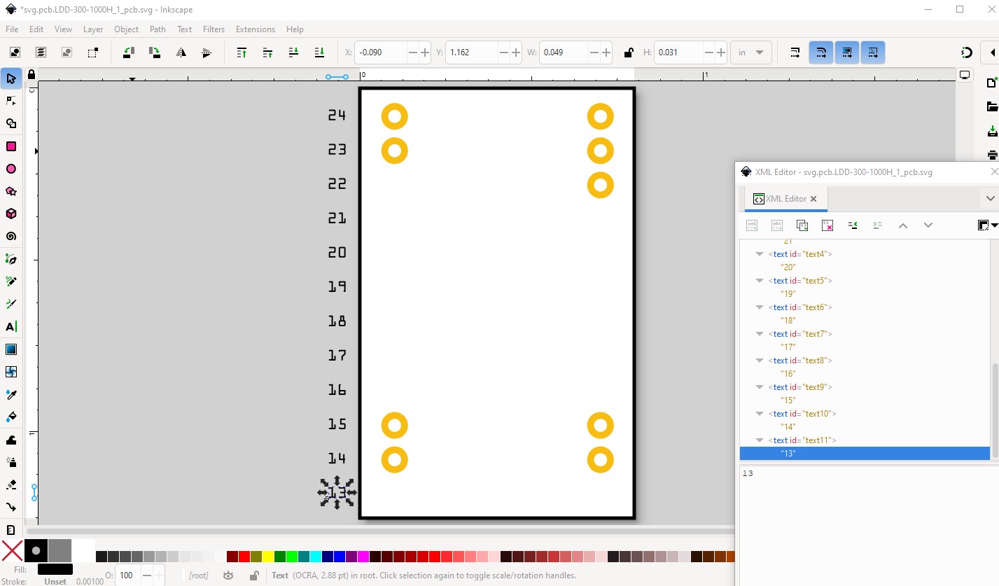
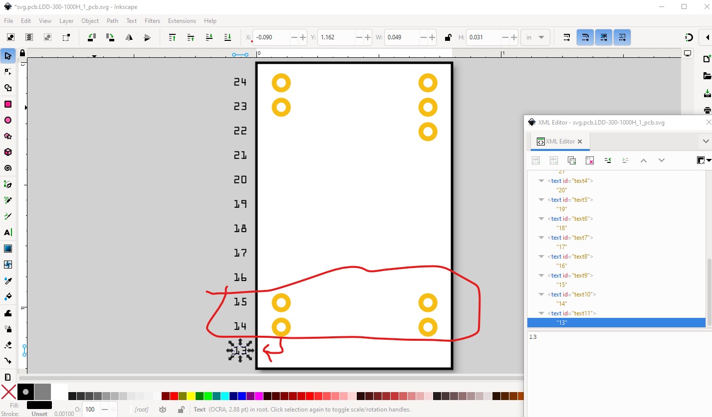
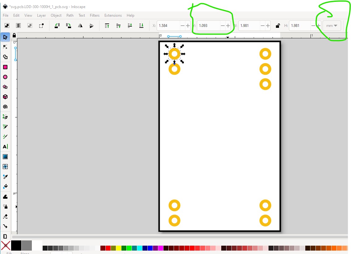
OK I found a second error (the bottom 2 pins are 0.1in too high) and corrected it and replaced the part yet again. You will need to delete the part and reload it again as before. Here is the error (the bottom pin should be at pin 13 not 14)
to correct it move the pins down 0.1in Now the first pin is at 1.093mm in Y
the bottom pin is now at 29.032mm giving 27.939mm center to center of the pins which should be correct (1.1in between pins center to center.)
Hopefully there aren’t any not any further errors but I guess we will see ![]() .
.
Peter
thanks, next try… thanks in advance!