Hope this can be useful for someone
MAX7219 LedMatrix Red Module.fzpz (10.4 KB)
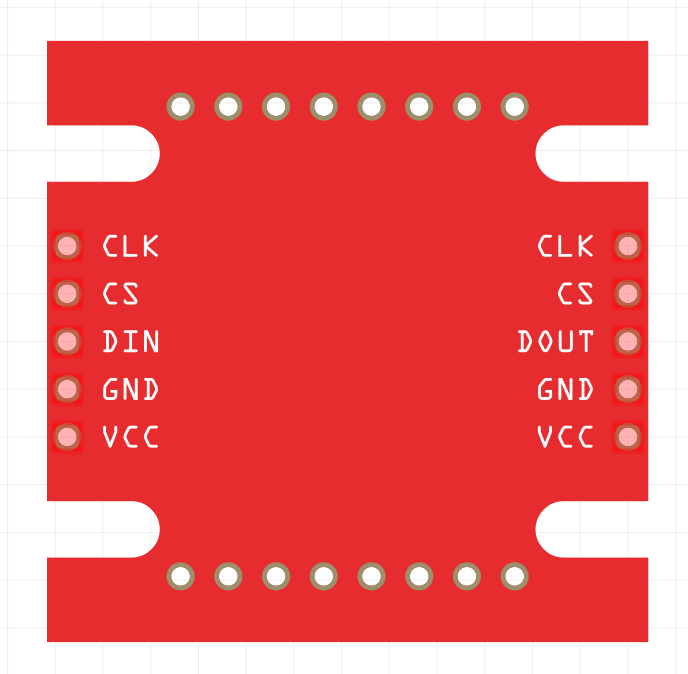
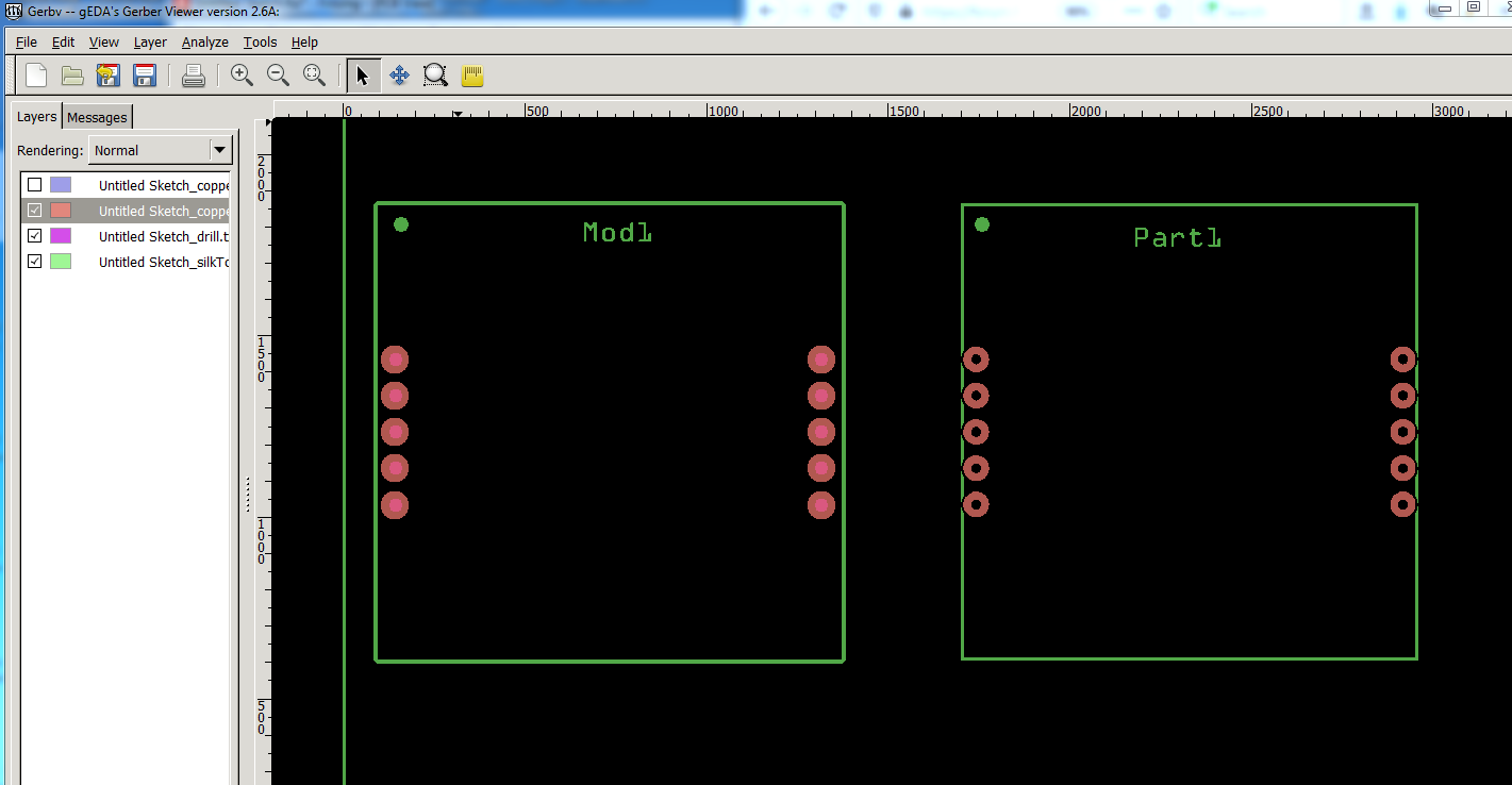
Welcome aboard! Over all a good part, with only one major flaw. In PCB the pads are defined as paths, which is fine if you are home etching the boards, but if you (or someone else) generates the gerber files and does not check the output, they will get no holes in the pads on the resulting pcb. As well the horizontal spacing of the pads is odd (but perhaps not incorrect) at 1.148in (I would expect a .1 in boundary such as 1.1in or 1.2in) something to check against the actual module to make sure it is correct. Below is the gerber output from my corrected part and your original part with copper bottom, drill and silkscreen followed by one with only silkscreen and drill (no copper.) As you see on your part there are no holes being drilled. In my part the holes are 0.038in suitable for a .1 header pin.
silkscreen, drill, and copper:
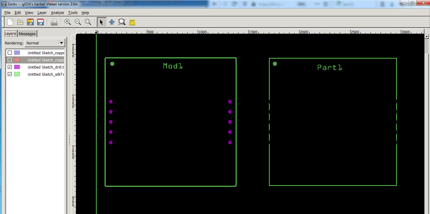
Silkscreen and drill only:
the purple circles on the left indicate where holes will be drilled.
Finally here is my corrected part, I changed the moduleId and variant so that it will load along side your original part for comparison.
MAX7219 LedMatrix Red Module-fixed.fzpz (8.0 KB)
Peter
Cool! thanks for your feedback, I think I will take yours to make improvements, regards
Ah, about the horizontal distance, yeah, it is odd but that is the distance in the module
Always good to check, as it may have been a scaling error (although not as likely as the pitch was the correct .1in, which is why I left it as you set it.)
Peter