Thank you, @vanepp , I noticed the same but it’s a little frustrating when giving written instructions to young people and they see something that doesn’t make the parts they were given.
If you have a data sheet or the web site of the module (to get connector information and dimensions of the part) you want I can easily enough make a matching part.
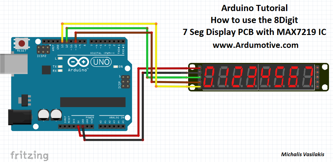
I take back that last message, the datasheet I found on Digikey is not what we’re using for this educational project. This is the correct datasheet for the Maxim7219 with an 8-digit display over SPI: MAX7219 DS (adafruit.com)
After vigorously scouring the internet, I found an SVG that’s pretty close:
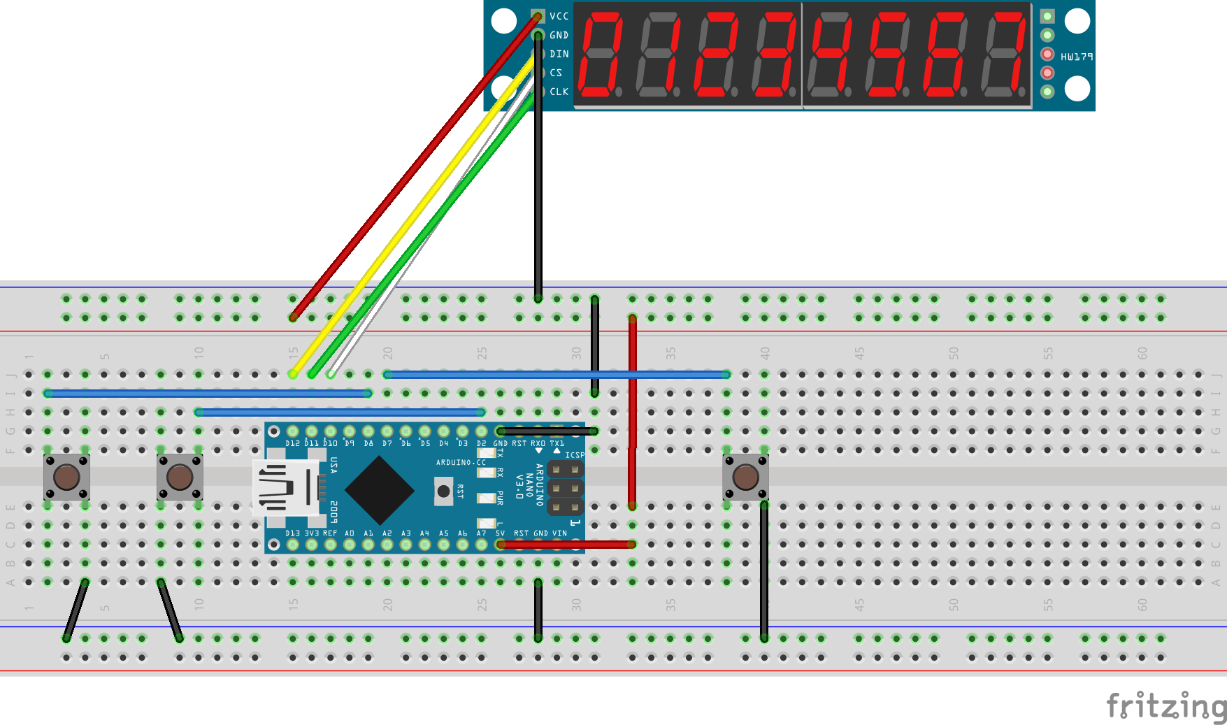
Given the 8x8 LED module uses the same SPI interface I used that as a base and replaced the breadboard and Icon images with this one. The pins on the left are input (ingang) and the left are output (aus) in order from top to bottom: VCC, GND, DIN, CS, CLK
Greater dimensional accuracy, and metadata in general, would be nice, but at least this looks similar to what the kids will see when they work on it themselves.