I’m still new but in perusing tutorials on YouTube (which conveniently avoided circuits that need this) and browsing I was left with the impression I was stuck with the wire placement that is part of the pic. Take the resistor, I can’t spread the wires to put them where they need to go.
Yet this person managed a work around or something. It the same circuit I’m trying to draw in fritz with a few components in different spots on breadboard.
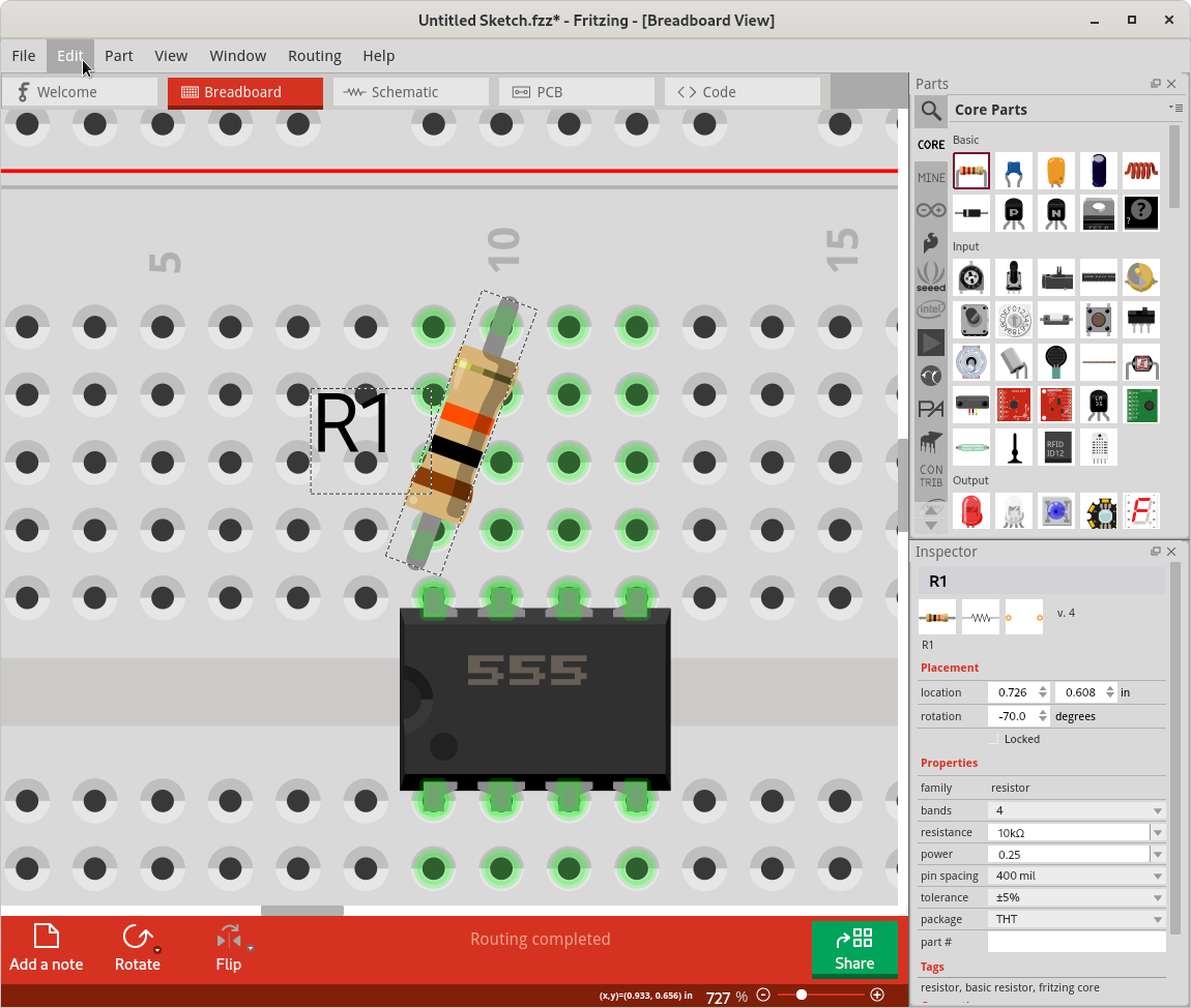
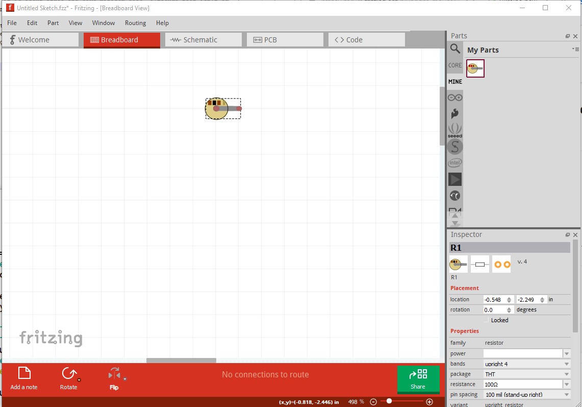
How did they get R1 to look like that. I can’t move the legs at all. And I want C1 to have two holes between the legs not one.
I want to be able to fritz the circuit I made, not make a circuit I’m forced to because of fritz limitations. I got fritz because that’s what the people I follow and read use, only they manage to make what they want, not something they settle for because fritz won’t let you move or bend inch long wires like in real life. I thought it would be easier that drawing a whole circuit by hand but I guess if I want my breadboard circuit to look like what I made I’ll have to go into mspaint or something. What am I missing.
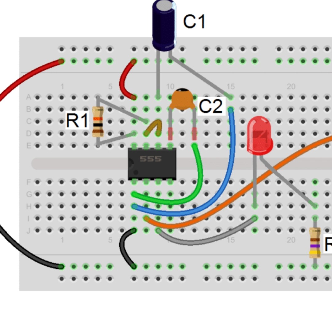
Here’s the circuit with the nice resistor and capacitor placement.
Some parts, like the resistor, capacitor, and led in core parts, have what are called ‘bendable legs’. After placement, the end of the wire (the red portion, when it is not connected to anything) can be dragged to a new position. The example you provided does not show it, but once dragged out like that, the extended portion can be routed the same as the wires. They can have bend points added, and can be turned into curves instead of straight lines.
That can also be used to ‘shorten’ the leads, by pulling them back towards the body of the part. For R1, here is the ‘trick’ I would have been tempted to use.
Here is what is in “tips and tricks”, it implys I should be able to drag with “alt” pressed and drag the wire out.
In Breadboard view, to drag a part with bendable legs while keeping it connected to the breadboard, hold the Alt (Linux: Meta) key down when you start dragging. In Breadboard view, to drag out a wire from the end of a bendable leg, drag with the Alt (Linux: Meta) key down.
I’m using Linux, and that does not seem accurate. Looks like that documentation has not kept up. I just click/drag the end of the lead, without using any modifier keys. Holding down ctrl key toggles whether bends or curves are produced when dragging the middle of a wire (or bendable leg). That is going to mix with the configuration set in Edit; Preferences. It also mixes with what grid is set, and whether align to grid is on.
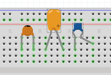
Here is a pic of a few capacitors. I want the round ceramic one but I cannot control the legs separately. Notice the other capacitors work as the documentation describes.
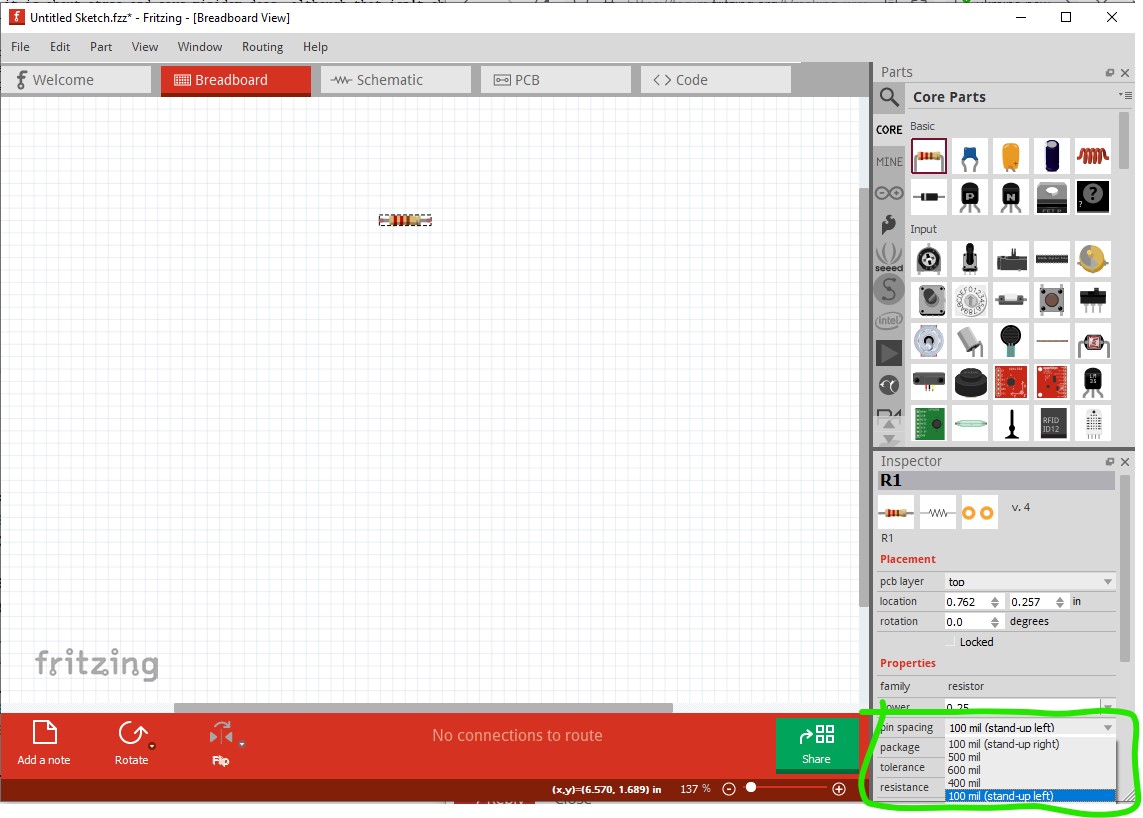
I’ve tried to change the preferences to curvey wire but it doesn’t save, when I back out it reverts back to default. If there is a “save preferences” it must be below the screen, and I can’t move that box to see.
I managed to move my resistor so it is over the jumper, just like in real life. That feature seems to work willy nilly.
Thanks to all for all the help. If the tips and documentation were consistent the learning curve wouldn’t be as steep.
A quick look (not at the source code of the part though) indicates it isn’t a bendable leg part and thus the legs won’t move. A version that does have bendable legs could be made though.
The base answer here is there aren’t enough resources to do that. My suggestion would be for you (as a new user) to document the parts that are confusing/unexpected/wrong/out of date and either fix up the documentation your self when you learn enough or at least post your list to give someone interested a starting point (although from several years of trying to get development restarted I don’t hold out much hope for finding “someone” …) For your resistor woes, there is a upright resistor with the color bands that fits in 0.1in (there is one in the resistor in Inspector here too, it doesn’t work in breadboard only pcb)
My screenshot tells me the preference window is 834 pixels high. You must be working with a low resolution screen. If your operating system allows it, you could try telling it that the screen is rotated 90 degrees. Screens are normally wider than high, so that lets you see further ‘down’.
There are “Cancel” and “OK” buttons at the bottom of the preference window tabs. For the curvy wires setting, click the check box, press tab 2 times, then enter. That should be the same as clicking OK, even if you can not see it.
To change settings that you can see on the general tab, after making your changes, click 2 times on the language line (opens then closes the drop down), then hold shift and press tab 2 times to get to “OK”. Enter or return should be the same as clicking.
I found a capacitor that looks like your example ‘round’ one. It is from sparkfun. Those have been added to the core library, but are not directly maintained here. As Peter said, that part was not created with bendable legs.
Another trick I have done with parts that do not have bendable legs, is to use a grey wire. Done carefully, that looks just like an extension to the lead.