I have some experience with fritzing but not making parts. Here is my question:
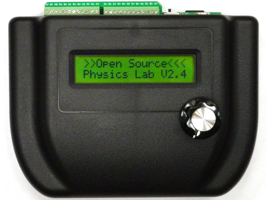
I have an open source data logger. I want to make it into a fritzing part so anyone including myself can easily make a wiring diagram. It has two 12-pole screw terminal blocks. The rest is just the enclosure. I have a decent image of my logger. I wonder if I can include images in fritzing parts. All I found online are making SVG graphics for parts. I wanted to start with a 12-pin header but I found the parts editor to be impossible to understand. Having designed circuit boards in EAGLE for several years, I don’t lack the knowledge of circuits. I just don’t know how to even start. Besides breadboard view, I could do a simple two 12-pin headers and not worry about sizes etc of this part on PCB since it is NOT going to be an actual part I need on a PCB.
Fritzing is easy to use in circuit creation, but making parts is a nightmare for beginners because FZ has features none of the other programs have.
Every part has to have 4 svgs and a XML file for the convenience of having 3 views simultaneously connected.
The breadboard could be your photo converted to a svg, scaled to 0.100" connectors and adding the connectors in the XML/.fpz
Icon can be created from the BB view.
Schematic is just a line representative.
The most important is a PCB view that has to be dimensionally accurate and have a certain XML structure, so that holes and copper are exactly in the right place and size for production.
.fzp file that is the actual XML file.
To learn I think it’s best you export a part, change the .fzpz to .zip, open it in Inkscape, and open the XML editor for the structure.
Once you know the format that FZ wants, you have to get into the really hard part of learning Inkscape.