Hey guys. I am building a shield for my arduino mega. The question i have is that i will not be using all of the pins on the arduino. If you add an arduino in your project all of the pins will be a hole in the pcb. ( so that you can soder a male header on)
I only need the pins that are connected to be a hole, this gives me the possibility to run the traces more compact. When there are holes the traces are not able to be generated at those positions. (because there is a hole ofc.)
This project is still a WIP, i will be adding more components. All analog pins will be used and the pins that are connected already on the schematic above.
Is it a solution to open the aruduino in the parts editor, go into the PCB tab, click the connection and press the X next to the name of the connection? Have not tested this.
Do you really want to remove the holes for all of the unused pins? That would mean that you can not pass those pin connections through to another shield, so this would have to be the last shield.
The Arduino needs to be part of your project to be able to show how the wiring connections work. It does NOT need to be on the PCB you are creating for your custom shield. Instead, position the Arduino outside of the PCB. Leave the connections from the Arduino board to the shield as ratsnest lines. That will show what is connected without attempting to create traces for those connections. If you want ‘real’ connections, you can use the wire jumpers.
All you need the arduino part itself for, is to verify that you have the correct relative spacing for the pins that will become the header pins in the shield.
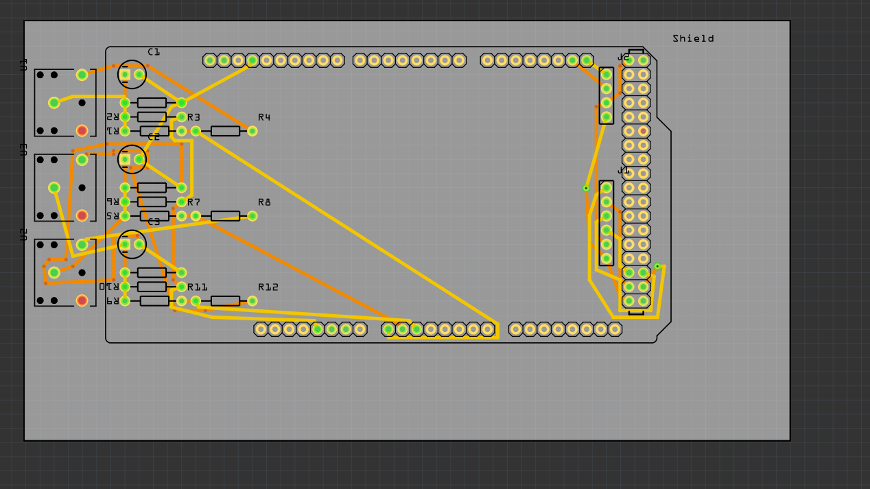
If you change the pads for the header pins from circles to oblong ellipses (actually smaller circle, plus overlay of hollow ellipse), there is room to run a regular width trace between them. That would help routing a lot. There have been some posts here on the forum to do that for raspberryPi Hats. The same would apply here.