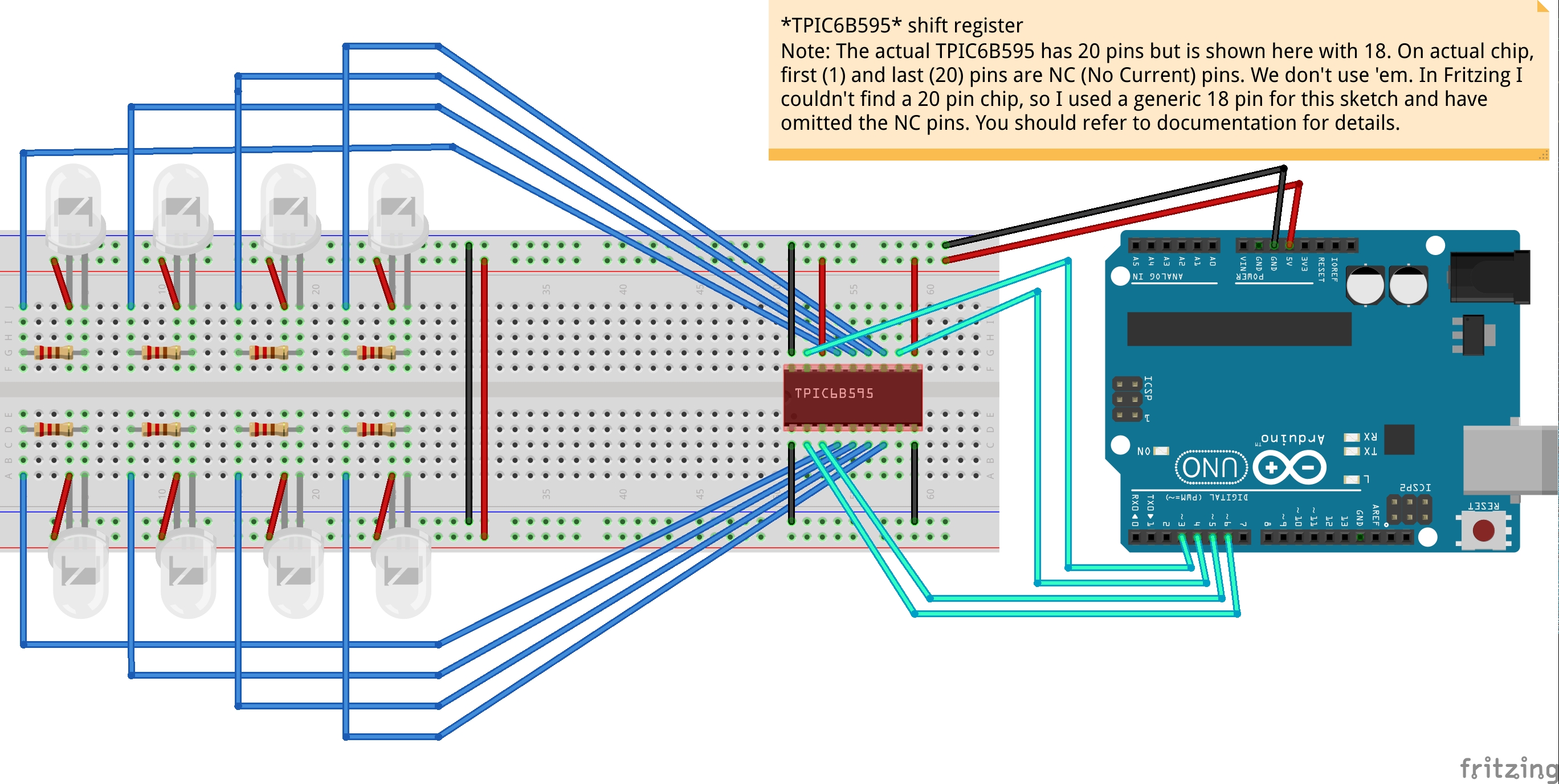
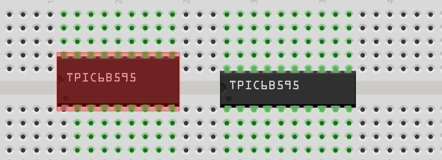
First Fritzing project. A bit overwhelmed as my first project uses a part not found. Stumped on how to create an svg for a 20 pin IC shift register. It’s similar to the 16 pin 74595 8-bit shift register, but the TPIC6B595 has 20 pins.
I’ve tried looking. In Parts, search “shift register”, see the resultant “shift register” with Properties/chip: 74*595, Select: Edit part. Then with Breadboard tab selected goto FIle/show in folder. I see pin varieties 6, 8, 14, 16, 18, 24, 28, 40. But no 20.
I’ve searched online, some, but no results in my first 24 hours.
So, can I make the image from scratch? Can I modify an existing set to change it’s shape and info?
I imagine I could just stretch an image and add 4 more pins to the image, then edit everything. But I don’t know if that’s even possible. I can only figure out how to edit metadata and connectors. I do not understand how to edit Breadboard, Schematic, nor PCB graphics.
Surely this is a mundane common stumbling block solved daily. But I’m overwhelmed by the tutorials and videos and just need to ask for help. Any assistance would be greatly appreciated and when we’ve solved this, I’ll add this handy little ic chip to the repository, to help out the next person.
Here’s some supporting info on the TPIC6B595 shift register:
(https://www.adafruit.com/product/457)
(https://www.ti.com/lit/ds/symlink/tpic6b595.pdf)
Thank you.!