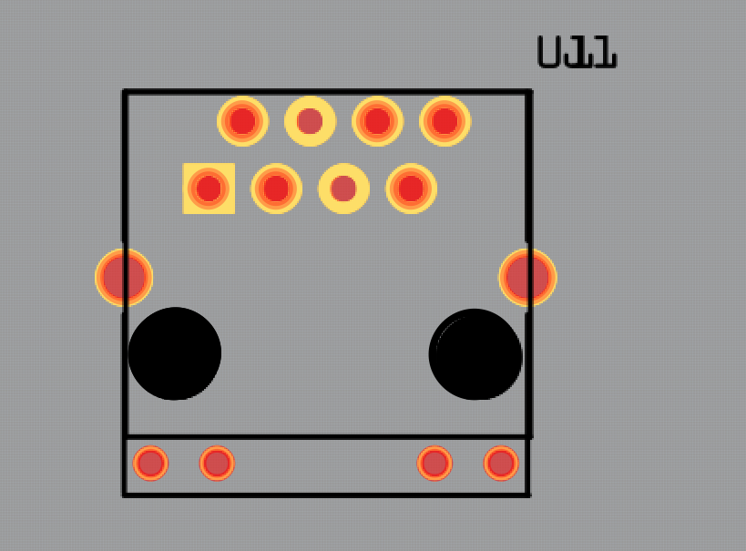
I was wondering if there is a way to modify the existing magjack footprint version in fritzing to use all 8 pins. I want to use this jack as a connector for analog signals. It contains 8 pins. but the magjack in fritzing has only 6 pins that are usable. The real reason i am going with this instead of the regular RJ45 jack is so that i can use shielded RJ45 cables to connect the two shielded ports to the ground. If i am correct this could reduce EMI. As you can see the Magjack connector below. only 6 points are usable. I would want to use 8 points to connect them to external strain sensors in one end. And use the Magjack on the PCB sides to feed signals to the electronics. Any advice?
If you add the part to a sketch and then right click on it and open it in the parts editor. After that you can change the pin number in the connections tab and then you can go to the PCB view and Schematic view and assign the new pins to the PCB pads and schematic since they are already have them in the SVG. Once you have all the pins assigned you just have to save as new.
Why not use the RJ45 jack in core parts? Has just the 8 pins, no diodes (which I assume you don’t want or need). There is also a Sparkfun load cell breakout board (but it has more than the rj45). Search for rj45 in the parts search bar there are around 6 different versions (with and without leds and magnetics, presumably you want one of the bare ones).
Once again thanks for the help. The reason i cant use the regular RJ45 is that it doesnt have shielding pads. And the MagJack is the only connector type which contains the shielding pads. But the parts which are available in Fritzing has two connectors that are missing and it is not editable to add them manually. Any work around this method?
Ok I just quickly opened the magjack in the editor and I see that the silkscreen is getting in the way of selecting the pads. This means the SVG will need to be edited to correct it. I think it may be that the silkscreen is in front of the pads and should be behind them in the SVG. I do not have time to look into it any further right now.
Could you tell me on how i may be able to do this? or is there an rj45 footprint with magnectics? as i dont see one there. i just need the 8 pins along with the 2 shielded ports
The first thing I would try is to save the magjack as a new part, export the part and delete the new part from Fritzing. Unzip the exported part. Open the PCB SVG in either Inkscape or if you are comfortable editing XML you could open it in a text editor and move the Silkscreen layer to above/before the Copper layer. Then zip the files back together and change the file extension back to a Fritzing part. After that you should be able to import the part and open it in the editor and hopefully the pads will be selectable in the editor and can be assigned now.
If that does not work then you would have to edit the SVG XML and add the correct pin/pad attributes to the pins/pads that are missing.
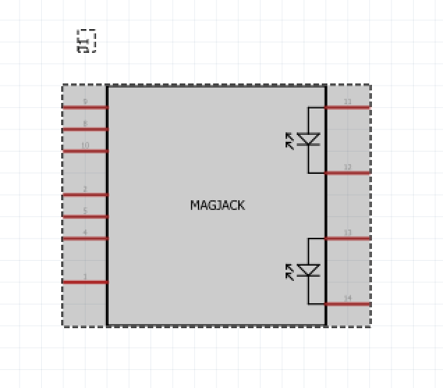
While it isn’t clear to me that this will do what you want (as the mag jacks have transformers for ethernet in them and are not a straight through connection) if there is a jack in the same form factor that has the shield and is straight through then this part will do what you need.
it is a modification (schematic and fpz file) of the mag jack that changes to 8 wires straight through to the pins. However I don’t know if they make such a jack without the magnetics.
Thanks once again. I hadnt known that magjacks had transformers in them. All that i wanted was a regular RJ45 with the option for magnectics. I hope that the shape of the footprint would fit the shape of a regular RJ45. On trying to see this in fritzing. It seems to be identical. But this should pretty much suffice Thank you so much
A quick look on Digikey indicates they make both types (shielded with and without magnetics), so you just have to find a part that matches this footprint (the footprints seem to vary) or pick a part and we can change the footprint to match.
I can fix that easily enough, but it would be best if I had the data sheet for the specific part you want to make the pcb footprint correct. There aren’t all that many shielded without included magnetics and the footprints are all different. Probably top entry or side entry matters as well. May as well get a part for exactly what you want.
Hello, thanks for the quick response and the tip.
I bought the RJ45 connectors and I still have to wait for the delivery from China.
So I don’t know the exact assignment yet. I just wanted to be able to select all the pins from the component. I can then pick out the correct assignment.
If you have the web site you got them from I may be able to find a data sheet (connections and pin layout.) Without that the part won’t be correct (as the current one is not, it assumes magnetics because I didn’t change the pin labels in addition to missing one pin definition.) I would rather have a correct part at this point rather than another cobbled together one. The changes are mostly done except for pin labels and footprint (both of which depend on the part!)
 Thank you so much