Hello!
Does anyone have the Luatos ESP32-C3 MCU Board part?
Thanks!
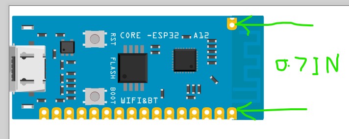
Assuming you physically have one of these, can you tell me the spacing between the pads horizontally? I assumed from the board dimensions (0.83in wide) that it should be 0.8in but in the svg that doesn’t work out with the 0.83in board width
0.7 in wide would work but still doesn’t match the scaled jpg image of the board (nor the stated width of the board at https://wiki.luatos.com/chips/esp32c3/board.html.) So I’m pretty much stopped til I know what the width of the pads should be. It may well be that it should be 0.7in as that would work with the stated size of the board but until I’m sure there isn’t any point in proceeding.
Peter
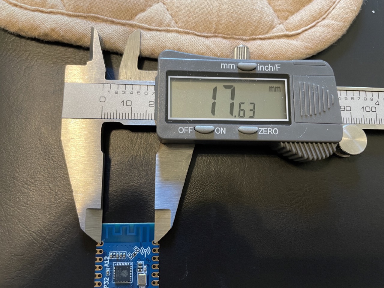
I went ahead and took the measurements in Metric as I think there is some bits of rounding to inches that is causing the measurements to be off possibly.
From center of pin hole to center of pin hole: approx 17.63mm
From edge of pin contact to edge of pin contact: 15.85mm
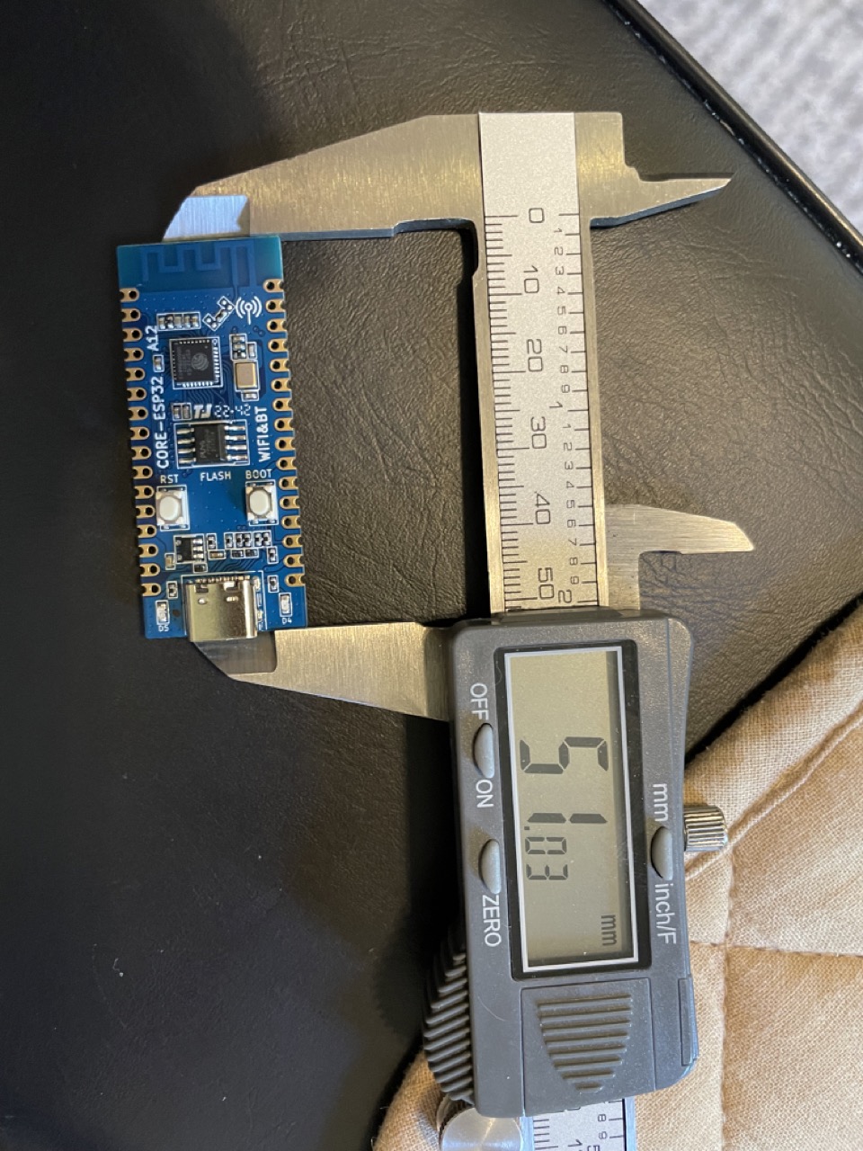
PCB Length: 51mm
Full Length (including the little extra from the USB-C connector that sticks out): ~51.5mm
PCB Width: 21mm
Let me know if you need any other measurements.
Thanks!
Good. Looks like the spacing should indeed be 0.7 in (17.63mm == 6.940944881889764in so round up to 0.7!) I had the pads a little wrong which didn’t help any but this should be enough to complete it. Thanks!
Peter
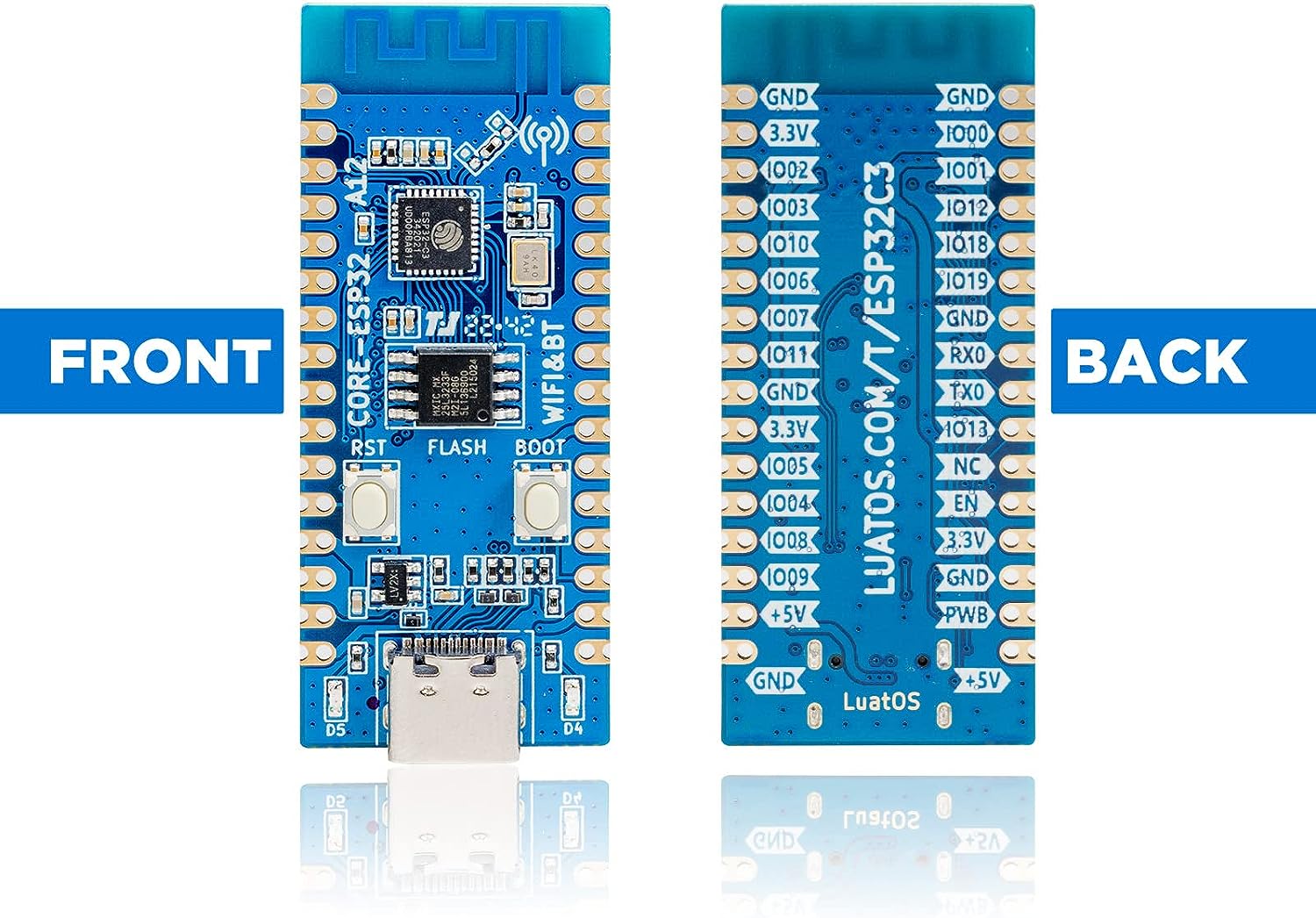
OK here are two parts. The tht one is for when you want to use 0.1in headers, it is through hole and will drill holes and has pads on top and bottom layer.
edit:
27 Oct 2023: The pin numbering on these two boards is swapped. The original parts have been replaced with a new version which has the pin numbering corrected. If you downloaded these parts before the above date you need to download the parts again and replace the old ones with the new ones.
Luatos-ESP32-C3-THT.fzpz (20.3 KB)
If you want to solder the part to the SMD pads (and potentially put parts on both sides of the board) use the SMD part which has pads only on the top layer and drills no holes.
Luatos-ESP32-C3-SMD.fzpz (20.2 KB)
Peter
Thank you so much @vanepp! ![]()
@vanepp So as I was wiring one of these up in Fritzing, I found that the wiring pins are flipped (incorrect). For example, on these parts the 5V pins should be toward the USB-C connector but they are laid out currently with the 5V pins toward the Bluetooth antenna. I think the pin layout itself is correct, its just flipped. So perhaps just the svg image needs to be flipped horizontally and that would rectify the issue?
Would you be able to make a fixed version of the part? ![]()
Thanks.
I’m working on fixing this. It is more complex than just flipping the svgs I think so may take some time.
Peter