HI i am looking for a 5v power bank module and a sim800l The sim that is in parts now does not have the same connections as the red sim800l with the antenna.
I have seen these parts used in the design so I was wondering if anyone knows where they may be. I have used google search and searched for these parts with no luck, Any help is appreciated Thanks
You need to provide a web page which has the modules you want before much that is useful can be done. A google search for “5v power bank module” brings up a lot of them. I assume the red sim800l is the alternate to the 800lV2 I made for someone a while ago, but a url to the unit you actually want would be required to do anything useful since that may not be what you want.
After I made this module, I read the sim800l manual. The sim800l under some circumstances can draw 2A and thus this power supply is not big enough. There are 2A boost modules readily available some even have Fritzing parts (the lm2596 for instance, which is recommended in the data sheet, is on core parts.) In any case here is the requested booster as it is made now.
The LM2596 is a step down regulator and thus would need 5V to produce a 4V output. You could (as they suggest) use a LIPO battery (3.7 to 4.2V) directly. Otherwise depending on your input voltage you may need to find a 2A adjustable output boost/buck module (which can take an input voltage both lower or higher than the output voltage) to power this. There are lots of such modules available and may be some with Fritzing parts. If not they are easy to create.
edit2:
OK here is the Sim module. Note the pin placement is from a jpg file and may well not be correct. Before ordering boards print out the footprint at 1:1 scale and compare it to a real board to make sure the pins are in the correct place.
edit (feb 2022)
replaced the part with one with the correct pin width (the pins are not on a 0.1in boundary!)
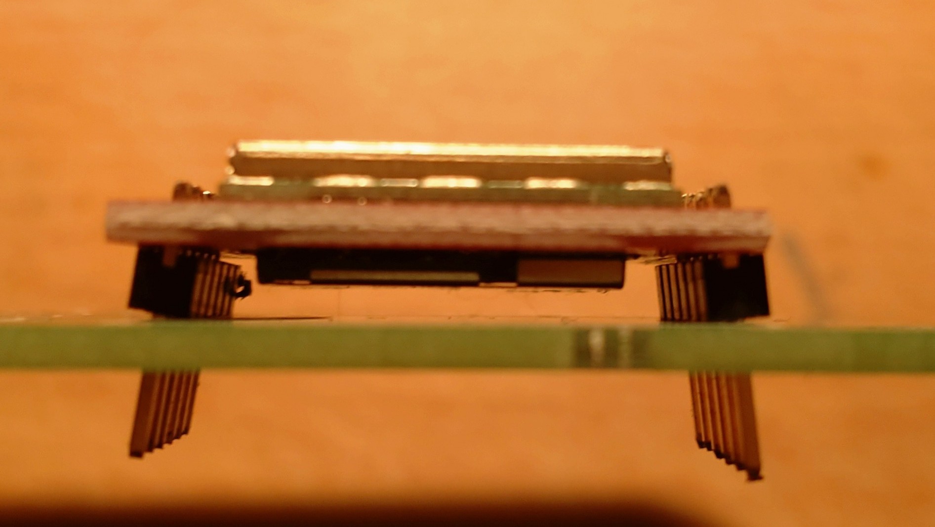
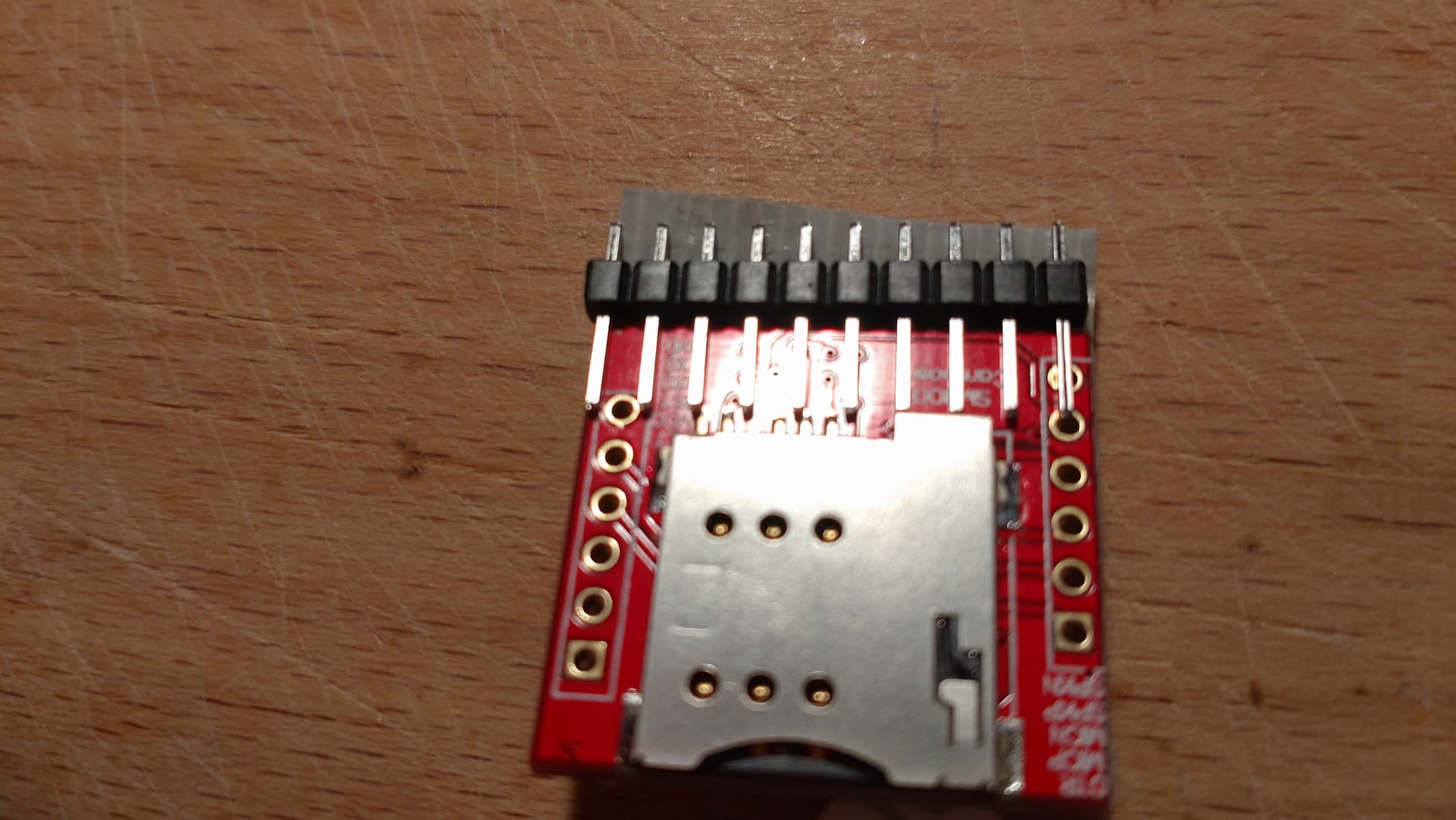
I have checked the pin distance on the PCB view and I think it needs some re-adjustment, seems on the breadbord view ok, 10 rows from one pin header to the other! This would mean 2.54 mm x 9 = 22.86 mm distance but seems – at least for my breakouts labeled “SIM800L coreboard” – a bit too wide:
Measuring is a bit difficult but I think 21.5 mm would be perfect!
It is not a big deal beause most people will use the left row only with the obligatory needed pins and leave the other side empty. But for stability I will solder this row also, even when not needed.
Can you try a .1 header across the board to see if the width is on a .0.1in boundary (i.e. put a header horizontal in the picture to see if the width is on a .1 in boundary as I assumed.) This looks like it may be one row too wide if the horizontal spacing is on 0.1in boundaries. It is easy enough to change the spacing to 21.5mm but it seems odd. To that end here is a part with the width reduced to 21.5mm. If you printout the pcb at 1:1 scale it should compare to the real part.
If this looks correct I’ll replace the original part.
edit:
from the jpg the 21.5mm does look more correct:
edit1:
replaced the original part above with the corrected one!
This is pcb from the corrected corrected part overlaid with the jpeg image. I may have noticed the spacing looked wrong on the original and thus the warning.
[edit] I have now replace the part in my fritzing layout, exported the design as PDF and printed out the [...]_etch_copper_top.pdf as 1:1. The result looks good and it fits with the module I have.
I’m not sure how many or if other versions are existing from the “coreboard”. So I would not count that this is the one and only design!
As always many, many thanks to you Peter! It’s a pleasure to have you here!