Type
I did not read this
Breakout board, sub assembly, plug in module (A)
Antenna (AE)
Battery (BT)
Capacitor (C)
Diode (D)
Display (DS)
Fuse (F)
Hardware , mounting screws, etc. (H)
Jack, fixed part of a connector pair, header (J)
Relay (K)
Inductor, Coil, Ferrite bead (L)
Loudspeaker, Buzzer (LS)
Motor (M)
Microphone (MK)
Plug, moveable part of a connector pair (P)
Transistor (Q)
Resistor (R)
Thermistor (RT)
Varistor (RV)
Switch (S)
Transformer (T)
Integrated Circuit (IC)
Crystal, Oscillator (Y)
Zender diode (Z)
Other (Power supply)
Footprint
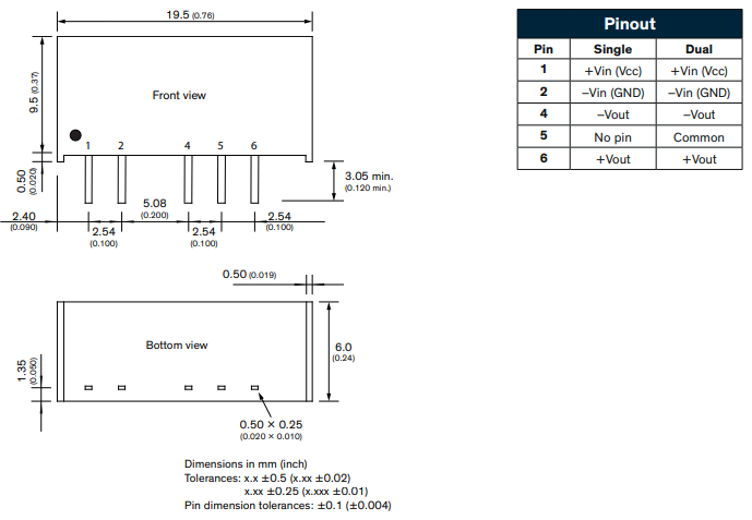
SIL 5 pin, device occupies the space of a 2x8 header (and has almost the same height as well)
The TBA 1-1222 series are a tiny DC-DC converter with varying positive and negative voltages (+15…-15v) with a power capabilities of 1 Watt. Worth noting: its generated output ground is isolated from the source ground (1.5kV). This makes it not only a simple and save power supply but also easy implementable level shifting.
Corrected a type in schematic where is says -vin instead of _+vout as it should. If you have downloaded the part already you will need to delete the part from your mine parts bin and the shutdown and restart Fritzing (answering yes to the save the part and save the part bin) to really delete the part before you can load the corrected one. It would help if I got the correct part though …
Thank you very much! I’m glad I have this component now as by using a molex 6 pin header as ‘footprint’ I oversaw two mayor space issues: The length of component and that the pins are aligned at the side of it instead of the middle (the component is placed at an edge of the board).
One minor remark in case other people will use the part, the label of the pin5 of the schematic view should be ‘+Vout’ . But I can happily live with it as it is now. 100 times better as my crappy solution. Tnx again!
The footprint is from this traco data sheet you posted and matches the diagram above (note the part is bottom view so will reverse in Y for top view, but the pins are not centered) is the part you have different than that? If so if you post the correct data sheet I can correct it. I have corrected the typo in schematic but will wait to correct it til I know about the footprint issue.
Sorry, no, your footprint is perfect! I made the mistake in having it aligned in the middle in my substitute footprint. I’m really happy with it. And the typo, it not of my concern but maybe others if you redistribute it (which I hope you do). Thanks again for your time spending on helping people. (I read your breadboard topic. I think the community is really profiting from your time and efforts!)