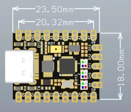
These two parts should do what you want (you will likely want the smd variant if you want smd.) Note to anyone else looking for this part there are at least 2 parts with the same name but different sizes. These parts are for the version above 23.5mm x 18mm. It likely won’t work for the other boards. As always before ordering boards print the pcb footprint out at 1:1 scale and compare it to a real part as these parts were made from jpeg images and may not be accurate.
Nano-V3.0-TypeC-smd.fzpz (21.0 KB)
Nano-V3.0-TypeC-tht.fzpz (21.1 KB)
Peter
I’ve been looking at this board off aliexpress
https://de.aliexpress.com/item/1005007492449786.html
and it is slightly larger, is this fritzing part suitable? I tried searching for Arduino Nano Ultra.
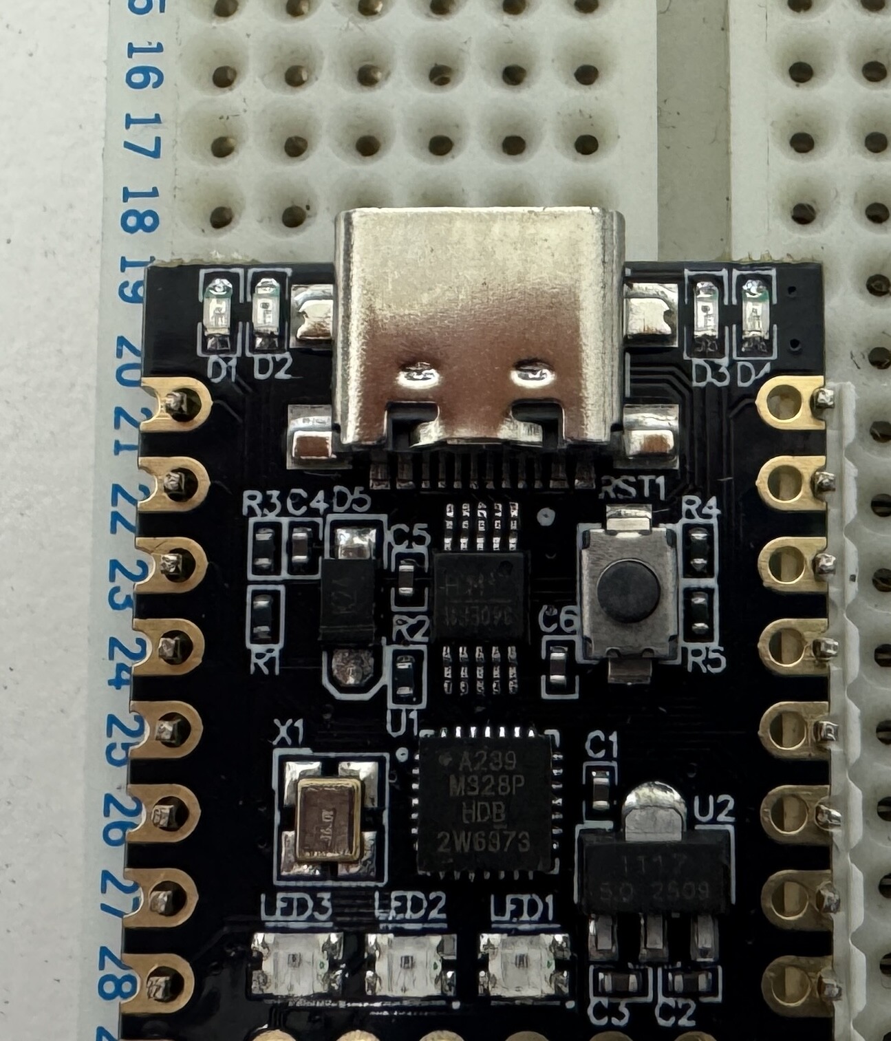
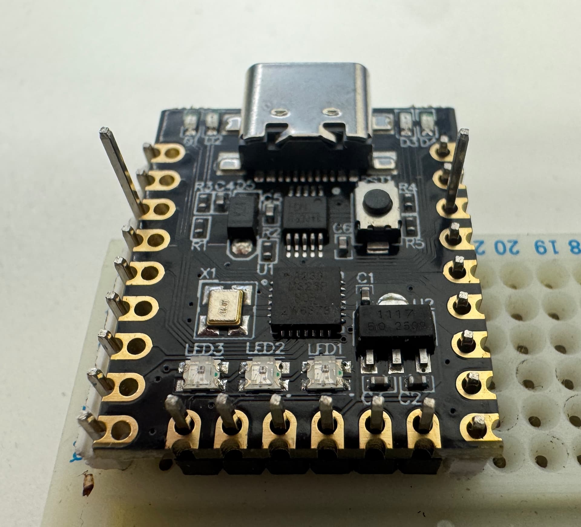
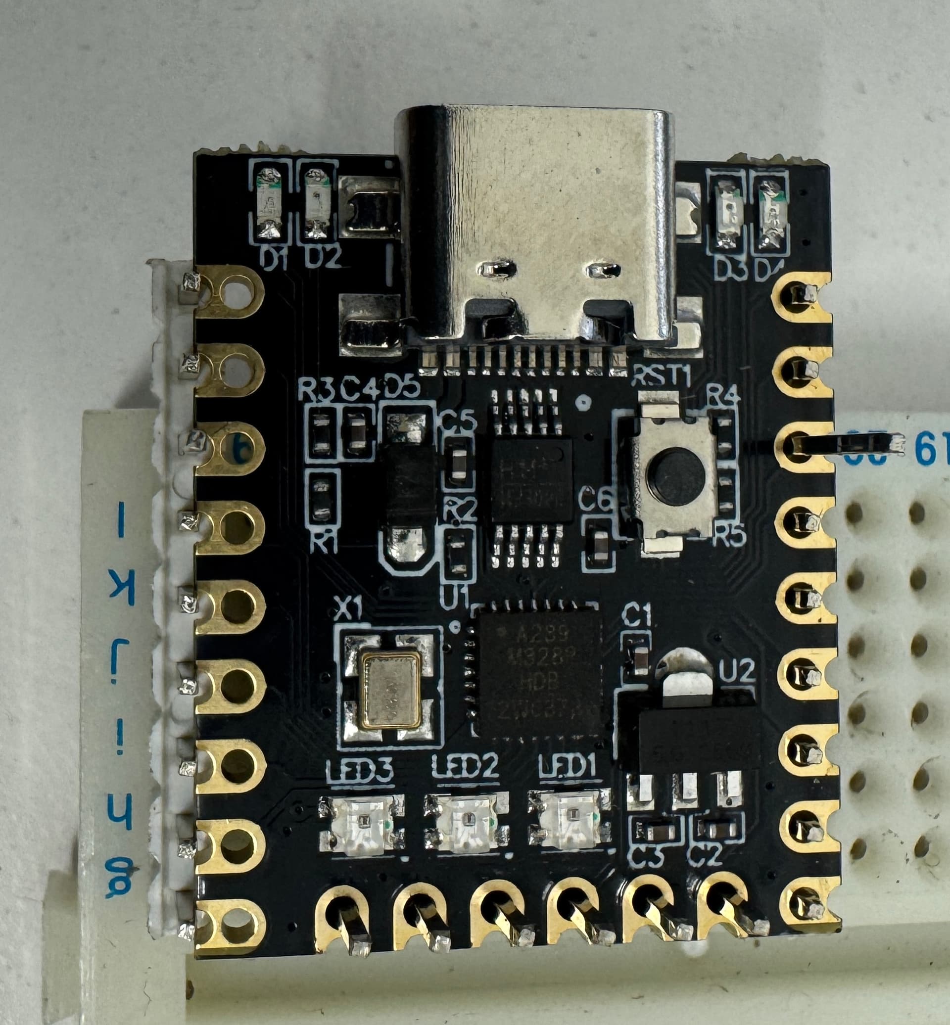
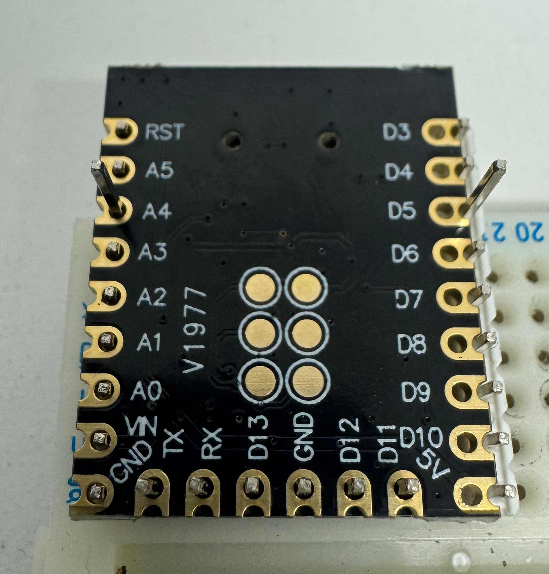
These are a couple of screenshots,

There is a pin out reference at the Aliexpress link, but if anyone can point me to a fritzing part I can download, that’d be great
Thanks
Mike
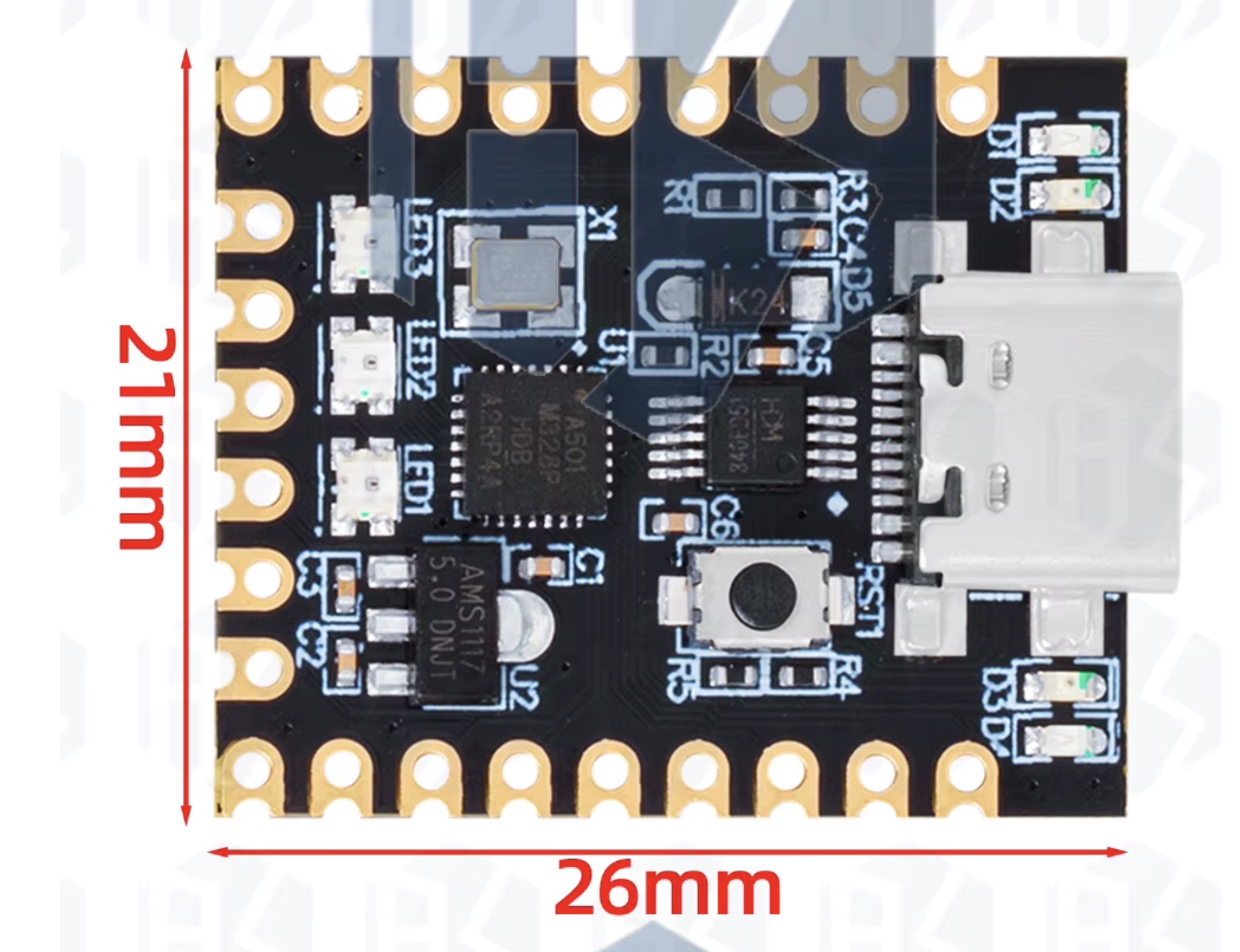
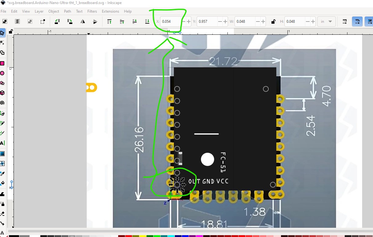
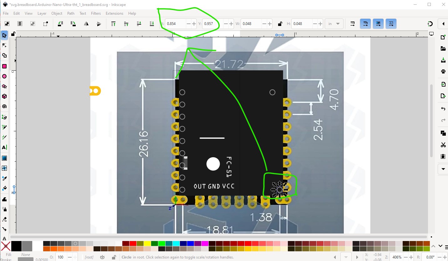
No the current part won’t work. It is the wrong size. It isn’t a problem (for me at least) to make a new part, but the measurements listed appear to be incorrect. This is the jpeg image imported in to Inkscape with the black rectangle set to the dimensions in the drawing and the pad spacing set to 0.1in with a 0.8in pitch. As we see the board appears to be wider than the specifited 21,72in. If you have one of these boards you could verify that the pitch is in fact 0.8in by plugging it in to a breadboard. Then measure the width with calipers to determine what the width should be. Alternately assuming the pitch is indeed 0.8in I could just move the black board out to match the jpeg image (because I am reasonably sure the pads are on 0.1in boundaries and the error is likely in the quoted number in the drawing.
Here the black rectangle is the specified 21.72mm wide, but the jpeg image (with the pads on 0.1in boundaries which match the scaled jpeg image) is slightly wider than that (and needs to be to allow for the half circle to the edge of the board!)

The pads are 0.1in spaced vertical and 0.8in from the left pad to the right pad horizontal which will match a breadboard (and is thus likely correct.)
and the other side which is 0.8in away.
If you (or someone else with a physical board) can verify the measurements are correct parts can be built.
Peter
Yes Peter, I have a few boards, so tomorrow I will do as you suggested and measure everything using vernier callipers. Thanks so much for looking at this, as I intend to make a PCB using Aisler for my car project,
Thanks again, I will add to the thread tomorrow.
Mike
Hi again Peter,
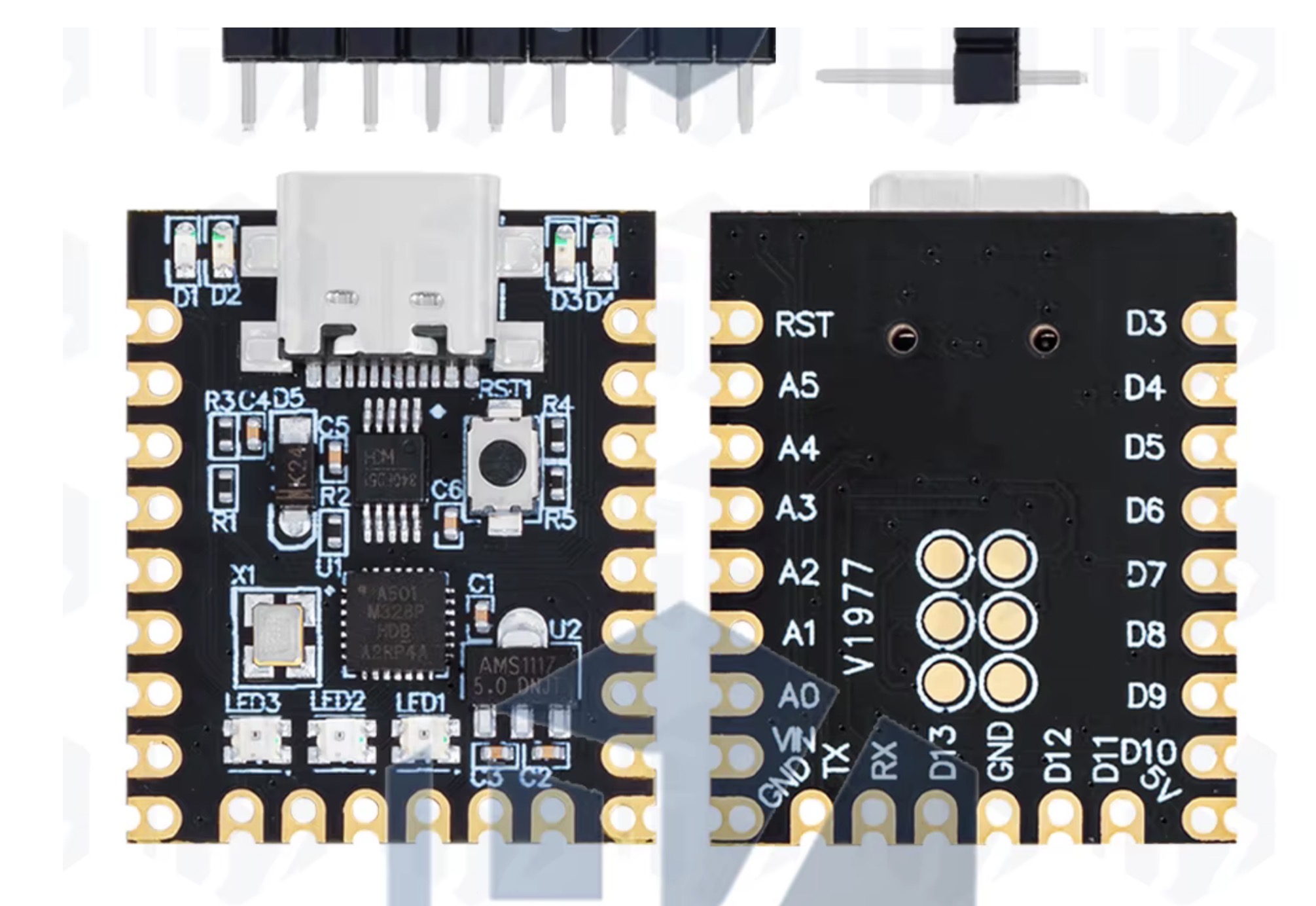
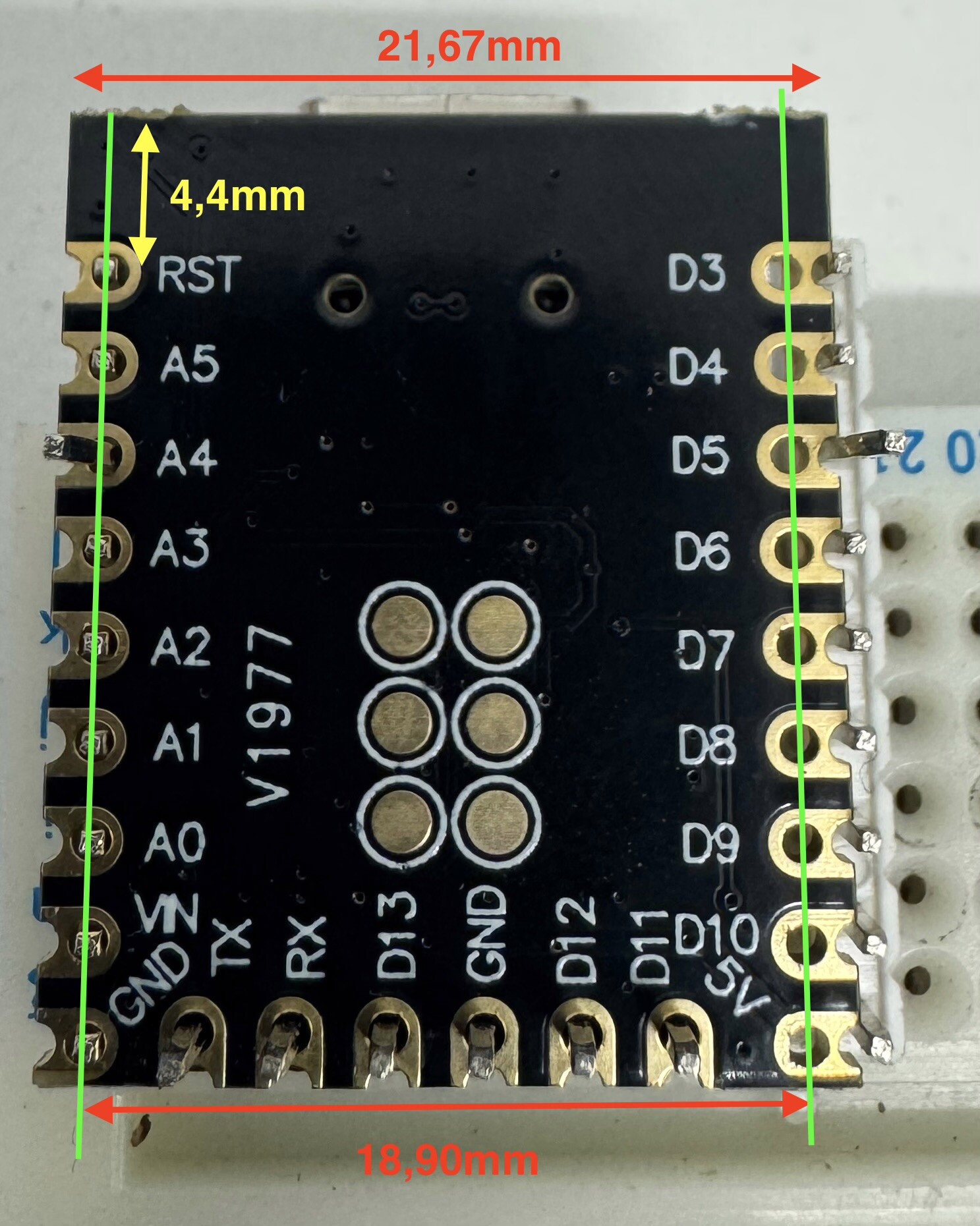
I’ve measured the board, and mine are 21,67mm wide & 26,49mm long. Unusually, the pins across the shortest edge (width) are not at 0.1” spacings, but from one corner they are, as you can see in the photos, however they land in the castellated holes on the other side if placed on a breadboard at 0.1” spacings. The pins appear to be 18,90mm between centres with each castellation hole in the PCB being 0.5” between centres from these. I hope this makes sense… the six pads on the underside, do align on a 0.1” grid taken from RST-GND side, so if this grid is “0” and the next to the left 0.1”, they are on gridline 0.3” & 0.4”. However they don’t align with the long edge 0.1” grid.
From the top RST pin centre to top edge of the board is 4,4mm, and the first pad centre (nominal 1,6mm diameter) is 14,4mm down, the next at 16,84mm, and next 19,3mm (as best as I can do without putting on a CMM machine)
I hope you can make sense of this using the pictures.
Thanks for looking at this,
Mike
So it looks like their measurements are actually correct. I will use them and your data to make parts. Very odd spacing though …
Peter
I agree Peter, very odd spacing, so I’m assuming someone made a mistake, and that’s possibly why they are so cheap.
Thanks again
Mike
That is likely the explanation OK nothing else makes sense. In any case these two parts may do what you want (the pad alignment may be off as I had to scale the jpeg to match the measured dimensions.) The tht version is for if you want to use headers and the smd version (which it sound like the one you want) is if you want to solder it to a board. Print out the pcb footprint (probably on overhead film is easiest) at 1:1 scale (the default) and compare it to a real board to see if the footprint is correct.
edit:
I realized the SMD part needs the ICSP connectors (or what I think are the ICSP connectors, there is no documentation) so I added them. The THT version doesn’t have them in pcb as they aren’t available through hole but they are in breadboard and schematic so you could solder wires to them. I have replaced the original parts with the new ones with ICSP pads.
Arduino-Nano-Ultra-smd.fzpz (17.1 KB)
Arduino-Nano-Ultra-tht.fzpz (17.1 KB)
Peter
Thanks Peter, much appreciated, and I will start this in a few days, as I’m working away from home.
I hope this addition will be useful for other folks too.
Mike