Hi everyone,
I’m looking for a part of scanner LIDAR , directly RPLIDAR A1 from Slamtec (RPLIDAR-A1 360°Laser Range Scanner _ Domestic Laser Range Scanner|SLAMTEC). Any help is appreciated!
Hi everyone,
I’m looking for a part of scanner LIDAR , directly RPLIDAR A1 from Slamtec (RPLIDAR-A1 360°Laser Range Scanner _ Domestic Laser Range Scanner|SLAMTEC). Any help is appreciated!
This part I made last year looks like it should do what you want.
edit: Replace the A2 part with a new A1 part.
RPlidar-A1M8.fzpz (108.6 KB)
Peter
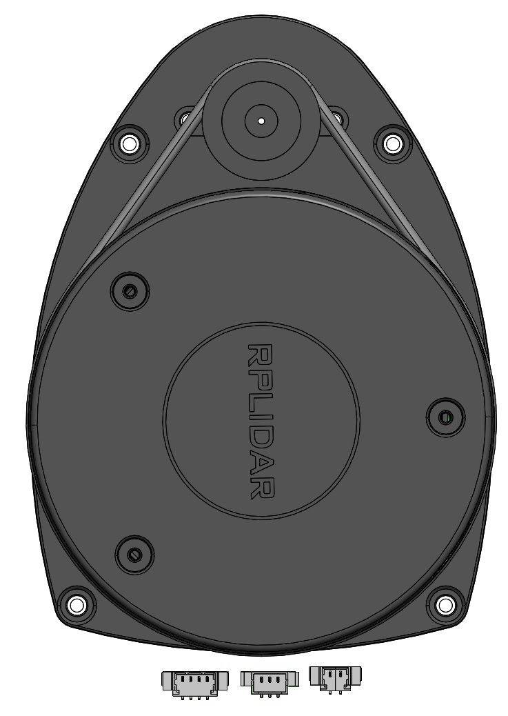
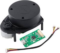
Hi, thank you for response. I had see that part. But unfortunately my scanner has 2 connection , first one is 4 pin , and the second one is 3 pin, the third one is not necessary. In attachment two picture.
I have found something which is similar to what i need but could not find, a part for Fritzing.

OK, I have replaced the part above with an A1 version. I think the placement of the pins is correct but it is worth a check (the pins are shown in the data sheet from the bottom not the top!) The position is approximate, if you want to use them in pcb first print out the pcb footprint at 1:1 scale and check the positioning! Also the mounting holes are only on silkscreen, if you want mounting holes in pcb you need to drag a hole form core parts/pcb over the hole in silkscreen in pcb view and set the appropriate size (probably 3mm.)
Peter
is there a way to show the labels for the pins
Yep. hover over the pin and its name will be displayed.
It is possible (but non standard, as they aren’t on the real device) to set labels on the pins in breadboard but that would require a new part.
Peter
thank you, i will just label them another way or use my schematic to show the labels. i appreciate the fast response.
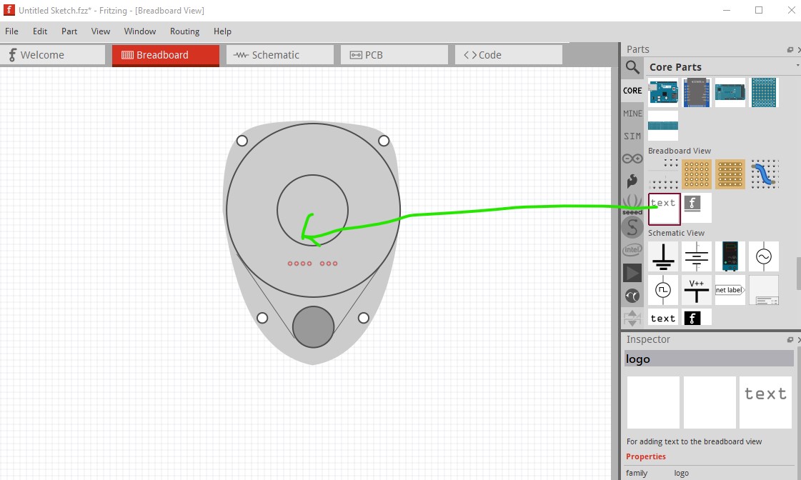
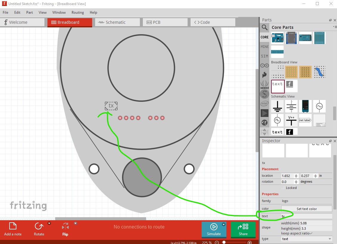
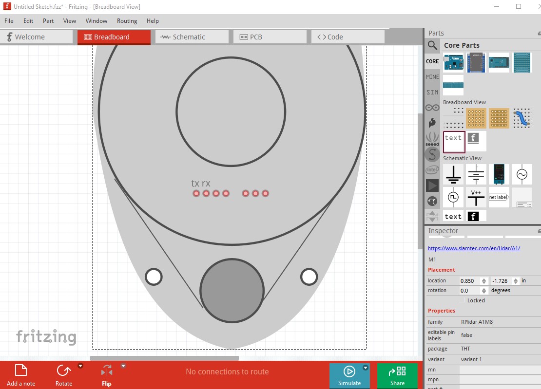
You can add text to the sketch which would allow you to label the pins.
You can set the text size and color in Inspector. It needs to be done on every sketch (where a new part is automatic) but it works.
Peter
thank you for all the support.
Can you create ttl to serial converter for this lidar? Like cp2102 in below. Thank for your help.
Images are useless in a part request. A web site with physical dimensions and connector information is required. A google search of the form “fritzing part cp2102”
turns up a variety of hits one of which may do what you want.
Peter
Sorry that I couldn’t find the physical dimensions of the part. The one in this datasheet is the one I am using. https://device.report/m/43682939e3646f8617611d8d25c49ef97216842e1fdc0ff0bc831245f84e8766_optim.pdf
For the lidar the RPlidar-A1M8.fzpz in the second post of this thread should be what you want. The pin out is the same as the device referenced. The interface board isn’t worth making as Fritzing won’t use it, there are no USB connectors on any of the CPUs I am aware of. You can load an image of the board in to breadboard via the image icon if you need it though.
Peter
I didn’t know that I can load image on breadboard. That has to be the way if so. Thanks for your time.
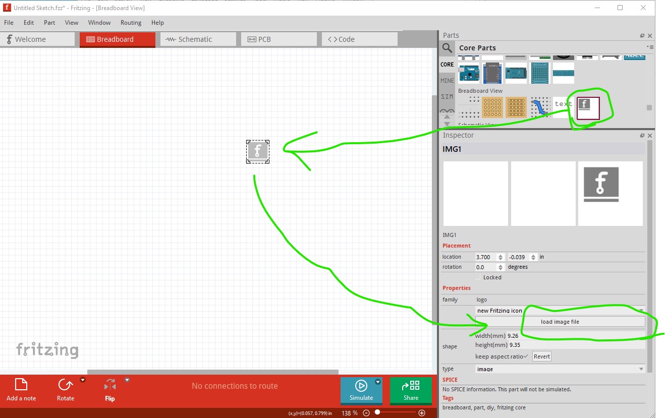
You do it like this, first drag the breadboard image icon in to the sketch (as it needs to be in a sketch before you can load an image in to it.)
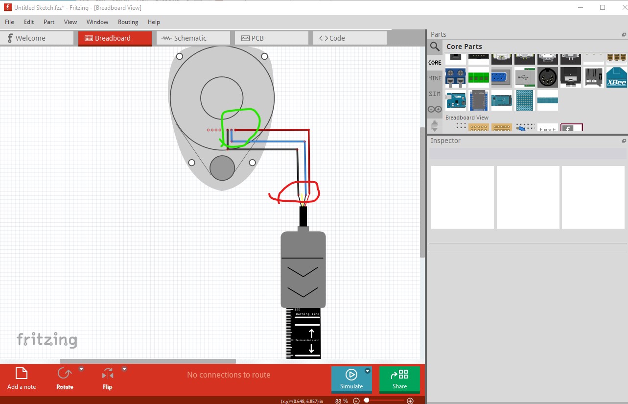
then click on the load image file icon in Inspector (the lower right window) which will allow you to load an image from the local file system. You would be best off with a svg image of the device you want (as it will scale with zoom where a jpg or other image file will not, but is more complex to make.) You can then run a wire from the lidar to the device (it won’t connect there, but will exist in the breadboard image) which should do what you want like this (which is the svg breadboard image of a dfrobot part imported as an image and attached to the lidar.
The lidar is connected (and where the wire must start) the image is not but the wire will end there and look connected. You would be best to find a cp2102 fritzing part and use its breadboard svg as the image you load. I don’t know if there is one with 5 connections, if there is you could just use that part and skip the image part of this.
Peter