Hi,
I need this Part for my Project. Can please someone create it?
A datasheet for more details: https://www.dhm-online.com/de/pdf-produktblatt?id_product=2145
Hi,
I need this Part for my Project. Can please someone create it?
A datasheet for more details: https://www.dhm-online.com/de/pdf-produktblatt?id_product=2145
No ideas? Or is that not much information?
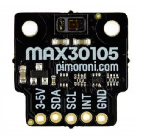
Pictures by themselves are not very good for making parts from. To create a ‘proper’ part requires dimensions of the board itself, and for the size and position of the mouting holes and connection points. Visually, that appears to use 0.1 inch spacing, but with an offset every other pin. It also appears that the larger holes are plated, so they might also be a connection. To ground maybe.
I located the part on the website, but the only datasheet I found there was for the max30105 chip itself. Not for the board.
Just to add this part to a Fritzing project, electrically, any I2C part (that includes an interrupt pin) will work. All Fritzing cares about is the 5 pins. Even if they are in a different order, that can be handled when wring up. Probably a PCB view is not going to be useful. With the intended usage for the sensors, it is unlikely to be mounted on a separate board. Just a cable to a micro controller.
So not really enough information to create an accurate part. And depending how you wan to use it, may I2C breakout boards will work fine for the sketch.
From the pimoroni web site (since it their board.)
Peter
Thank you very much for your information Merlin, I really appreciate it!
Wowww thank you Peter, you helped me a lot with that Part! ![]()
I was at their site too. Missed it. All I found was the datasheet for the chip, not the board.
A google search for “pimoroni max30105” brings up their store site
which has all the info needed for the board.
Peter
Curious. I got to that page as well, starting from the labelling in the initial image instead of searching. I just did not find dimension information from there.
But you found it, so thumbs up ![]()
Hi, sorry for bothering you again… but is it possible for you to create a part of the frontside of the module?
It is possible but non standard. Normally breadboard is from the top as that is how it will mount on breadboard. The pins will be wrong in the direction you are asking for.
Peter
I understand, anyway thank you very much.
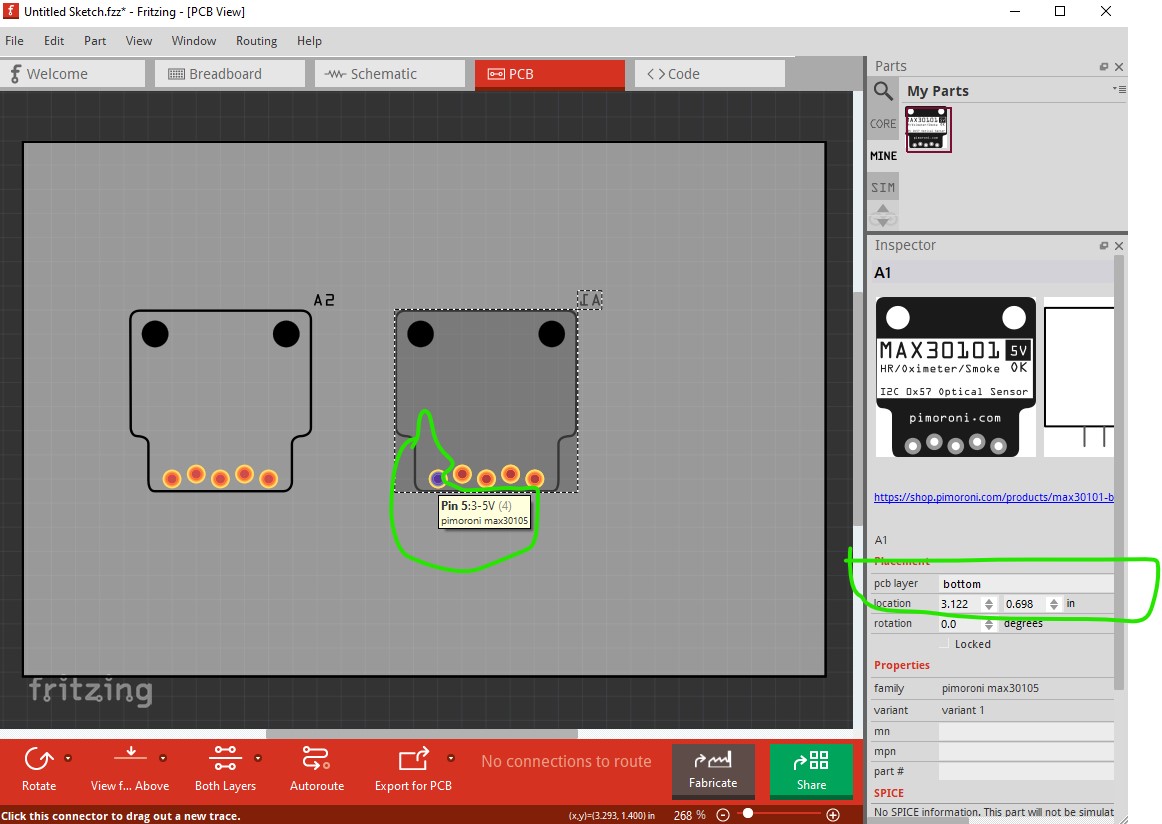
It is easy enough to do if breadboard is what you want, however the thought strikes that you may be wanting to put it on the bottom of the board in pcb in which case you only need to move it to the bottom of the board like this to achieve that. Here I moved the part on the right to bottom of the board in pcb which inverts the pins (and sets the sensor facing downwards where it can detect things under it rather than in to the board which is I think likely what you want.)
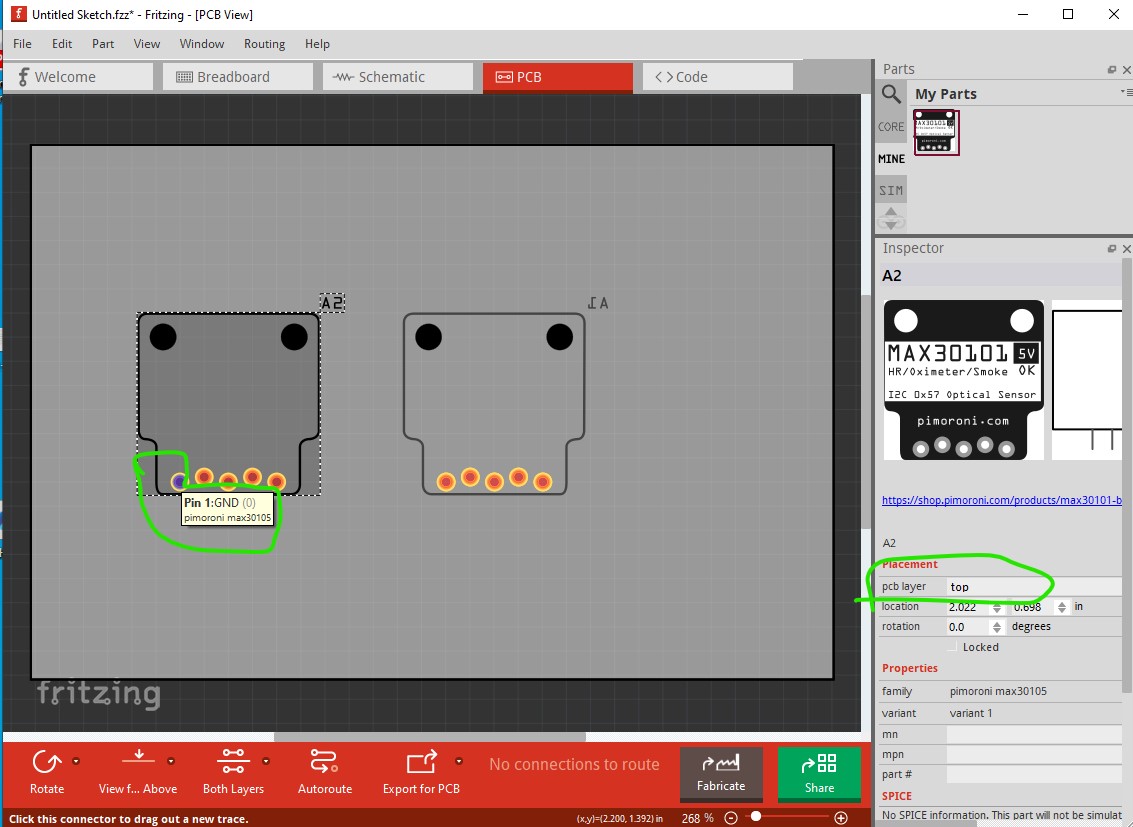
as opposed to the standard top view which will have the sensor facing the pcb and thus unable to detect anything on the left.
Peter