The current pin layout matches a PCB variant of the actual part, unfortunately, the URL links to RA4520F-10-20D1-B5K on mouser where that ‘10’ refers to the solder lug variant. I get that its not a standard way to do boards, but as I now have a bunch of the solder lug version in house, I would like to modify the part to match.
I’ll try to get the digital data from the manufacturer. It’s really just about making sure that the slider will fit your printed circuit board (PCB) later, right? For now, I’ve requested the data for the slider RA4520F-10.
So the slide potentiometer in the core parts bin was what I was thinking about just making a solder lug version. My intention is to treat it like a pcb mount part with extra big pins if you will.
Looking at the difference between the pcb mount version and the solder lug version in the data sheet, the existing slide potentiometer in the core bin should just need the holes enlarged I think?
Am I even on the right track to request the footprint for the Slider RA4520F-10.
Once we have it, you can simply replace it in the component editor and save the slider as a new part. The mounting solder pads would then be left unconnected, or just set them all to GND. I think the editor complains if they’re unconnected.
Maybe I’ll get the footprint tomorrow.
Of course, you can also export the slider, unpack it, and then modify the PCB file…
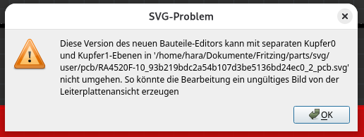
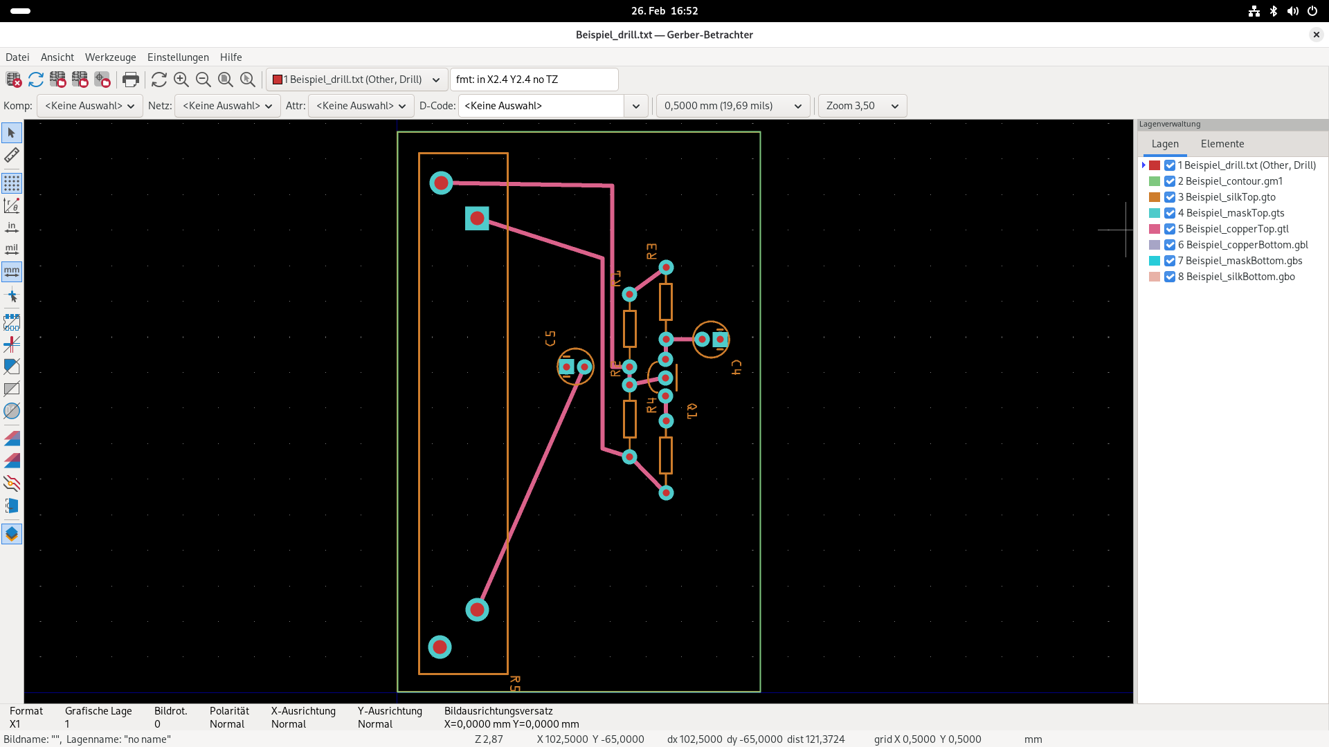
So, I’ve found a workaround. BUT that’s certainly not correct. I now only have a copper0. There’s no longer an error, but during the Gerber export it warns about the missing copper layer. However, in the Gerber viewer the file drill.txt is included and also shows correct values.
I’ll upload the interim solution here; this is not a final solution.
Alright, I’ll try asking a specialist again. Since you really want to have a board manufactured, it would be unfortunate if the drill holes turned out not to be correct.