Hello all,
New to the forum and to Fritzing,
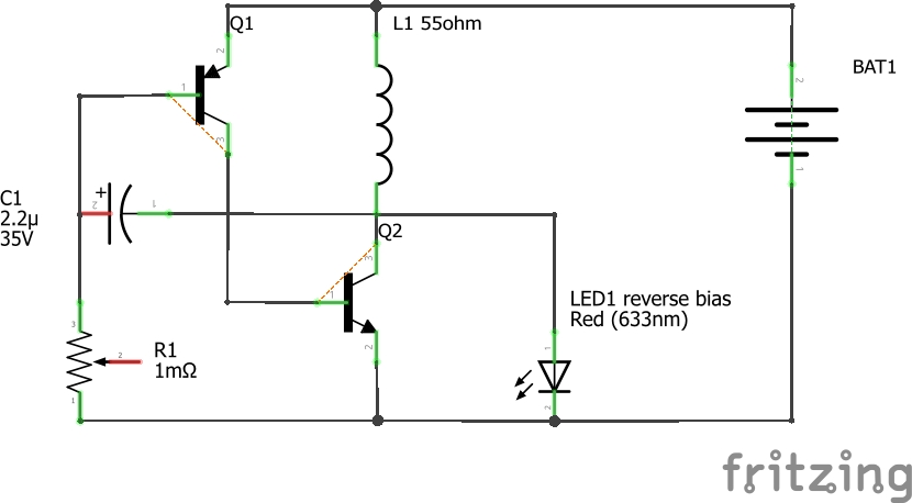
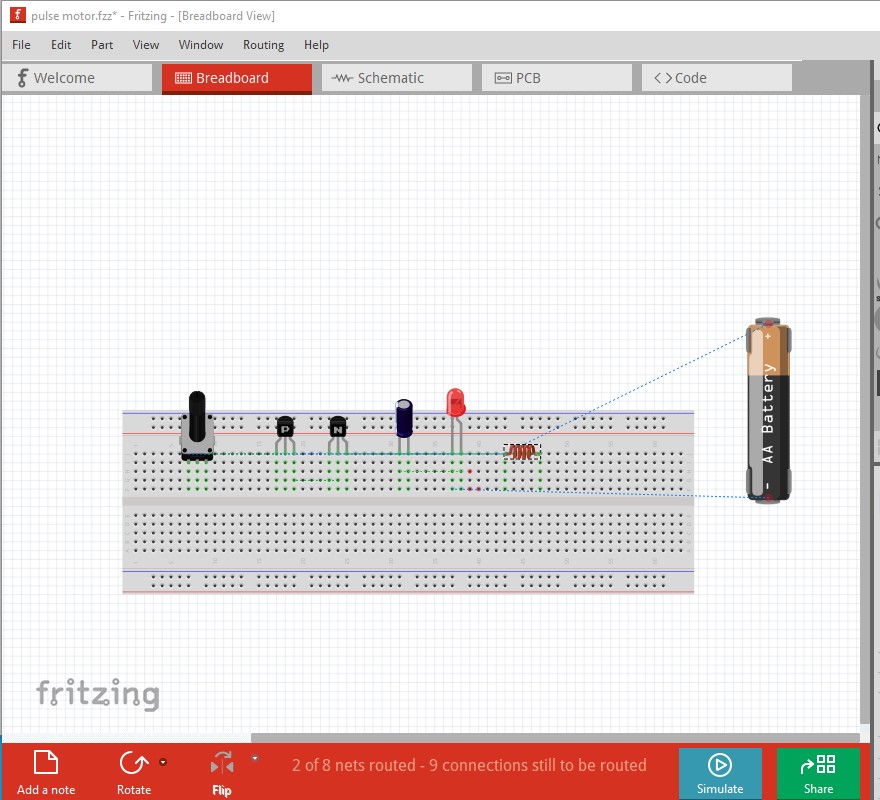
Looking for help with this circuit which is a LED flasher circuit modified to run a small pulse motor.
Circuit is from YouTuber Lidmotor. Can someone tell me what is wrong? Also the LED is connected reverse bias. The coil is 55 ohm.
Thanks in advance
pulse motor.fzz (5.5 KB)
Welcome aboard! You would need to provide more details of what you want to do for anyone to provide any assistance. A pulse motor circuit could be almost anything. There are lots of pwm motor drivers available for Fritzing.
Peter
well I am getting ahead of myself I do not see how to attach a .fzz
You don’t attach a .fzz, it is a sketch file you double click on it and it will load in Fritzing or select File->open and select and click on the .fzz file to load it.
Peter
I have it open do i share it?
if so share is not available
Normally you would either look at it or modify it, or export gerber files to create a pcb. I think sharing is used to create projects and I think that projects may have been disabled.
Peter
It is attached to my first message now need help correcting it
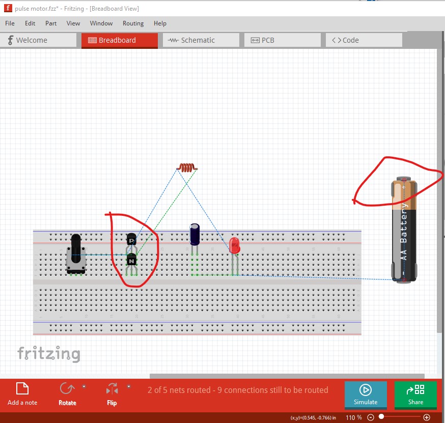
Ah! I read your initial post before it had completely uploaded and thus missed the .fzz file. You have a number of problems mostly to do with that connections in breadboard and pcb (and thus errors in breadboard and pcb) reflect in to the other views. In breadboard the transistors are shorted to each other (because they are in the same vertical strip and thus connect to each other) which causes the shorts in schematic as the connections reflect there:
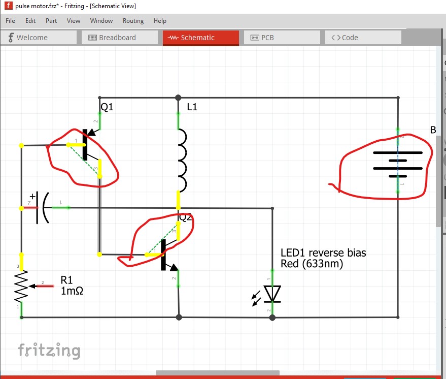
in schematic the rats nest lines (circled in red here) indicate the shorts reflected in from breadboard (here I right clicked on the base of Q1 which lights yellow everything that is connected to the base which is way to much!)
to correct that I fixed breadboard like this by moving all parts to separate positions on the breadboard.
that mostly corrects schematic like this
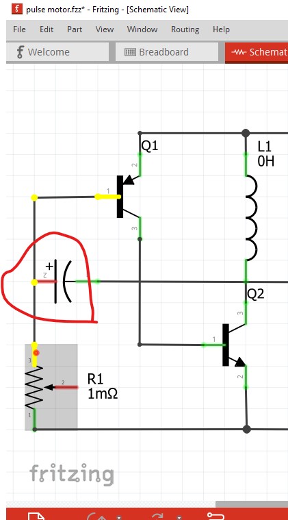
The problem now is that you can’t (and haven;t) connect the capacitor positive terminal to a wire it needs to be either via a wire to the top of the pot or to a bend point in the wire to make a connection (again right clicking on a connection indicates the capacitor is not connected as does the red of the capacitor + connection.) That should get you started towards successfully implementing this.
Peter
Thanks so much for your help. My understanding of electronics is poor, but I have a desire to learn.
Thanks again.
In this case it is more a matter of how Fritzing works than electronics. So if you have more questions feel free to ask, usually one of us will have an answer.
Peter
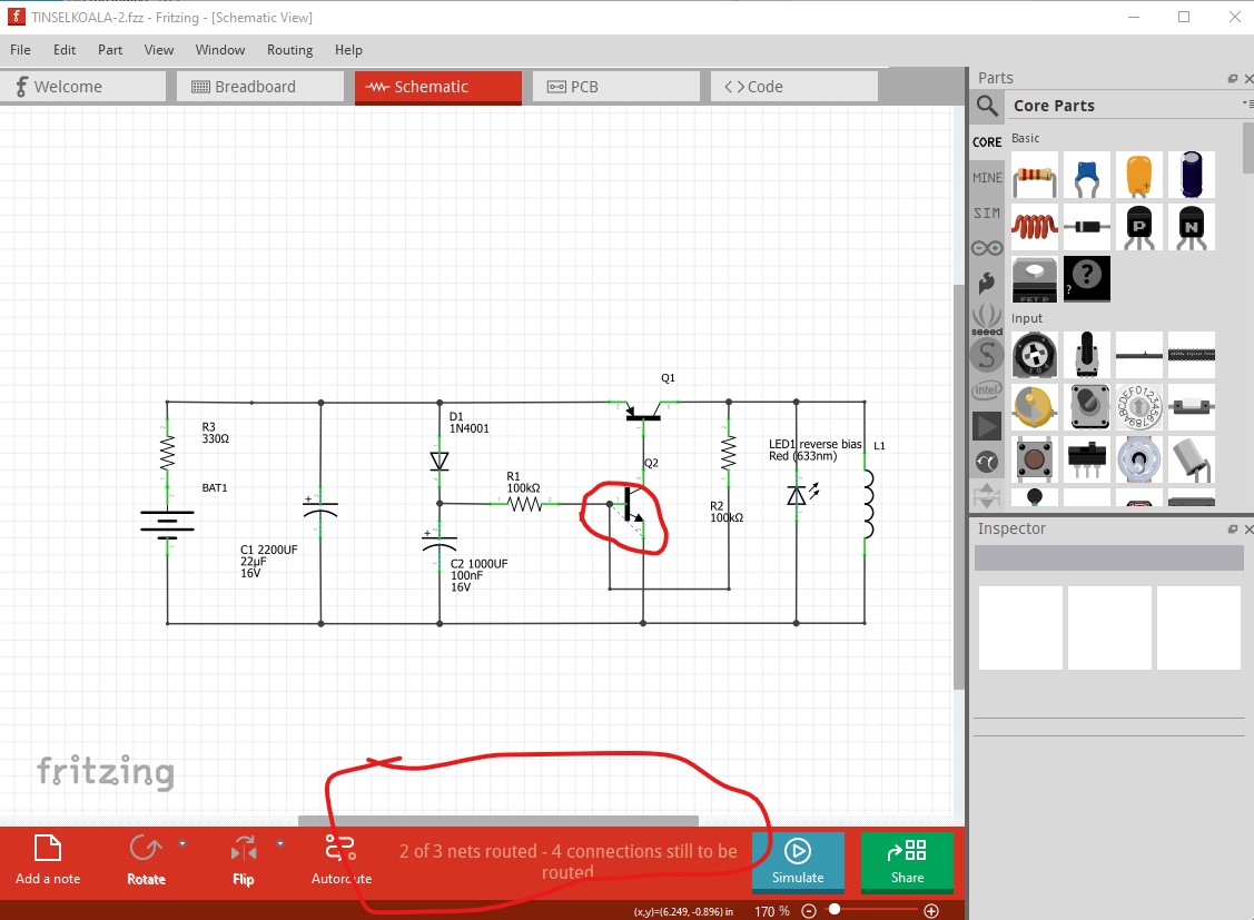
Still working on this pulse motor circuit. Schematic is correct according to what I have.
The battery does not explode. Could someone check it?
Thanks.
TINSELKOALA-2.fzz (13.5 KB)
Breadboard is wrong. In schematic there is one net unrouted (because of breadboard) and a short between the base and emitter of Q2.
Here I did route-> Select all traces then delete to delete all the wires. Then clicked on an empty breadboard column. As you see from the yellow dots all 5 pads are connected to each other. That means the diode D1 is shorted because it is connected to the same column.
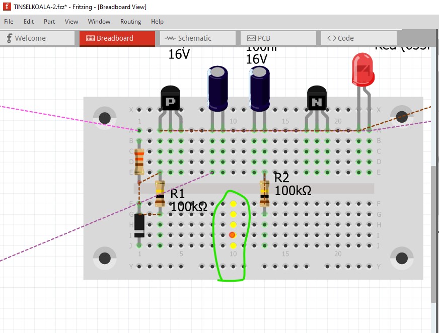
You need to move the components so none of them short like this (and move the coil on to the breadboard)
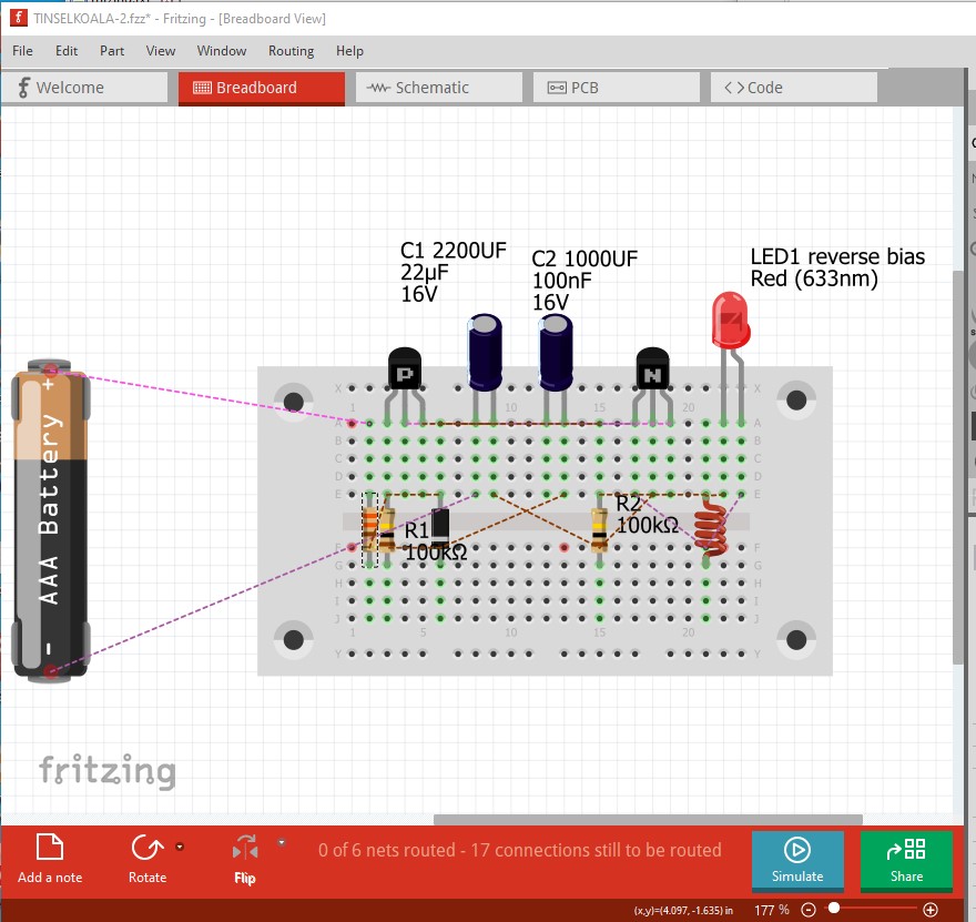
now you can click on each rats nest line to route it and route the wire to the correct connections and it should then match schematic. Schematic looks incorrect to me but I don’t know what this is supposed to do so I can’t correct it …
Peter
Circuit is an Auto Triggered Pulse Pendulum
I believe I have the Schematic drawn the same.
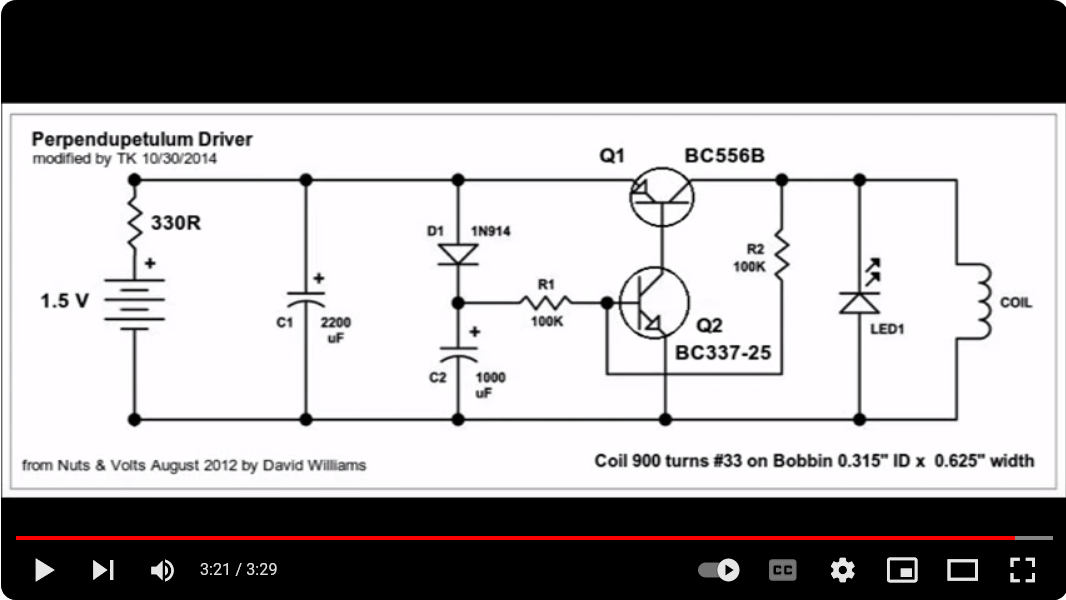
Auto Triggered Pulse Pendulum
I deleted each component one by one then in groups still can’t find the short?
Thanks.
The schematics appear to match, the circuit is somewhat odd but may work.
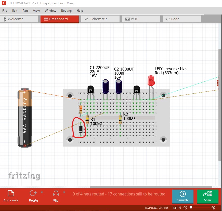
Did you do routing->select all wires then delete to delete all the breadboard wires then move the components around to match my image above? The short is because there is a short across the diode in breadboard because the 5 vertical breadboard pins are all connected together (bottom and top) and the breadboard connections reflect in to schematic and pcb (thus causing the shorts in schematic)
if you move the components on the breadboard to look like the image in my post then click on and drag each rats nest line breadboard should be correct (because schematic looks to be) and there should be no more shorts. If you click on a pin Fritzing will light yellow everything connected to it. There shouldn’t be any unexpected connections in any view.
Peter
Hello
Are you left clicking on a row to show the short? If so I show the red dot for short on an empty project. I must be missing something?
If you click on a vertical row of the breadboard like this
it will light the entire row indicating they all connect together. The diode on the left side is therefore shorted because both pins are connected to the first row and are therefore shorted together.
edit:
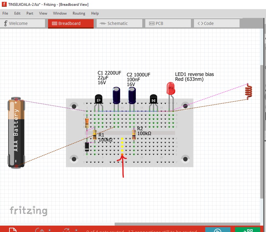
With some time on my hands I fixed breadboard for you by doing what I suggested: deleting all wires, moving parts to more sensible places then routing the wires one at a time.
TINSELKOALA-2-fixed.fzz (13.4 KB)
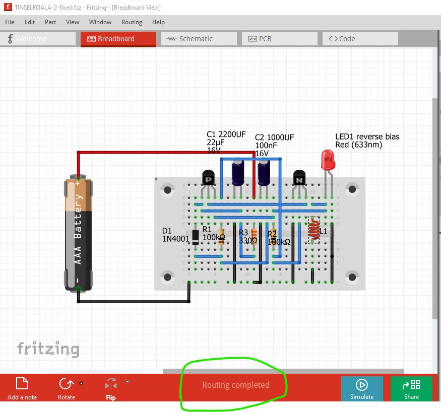
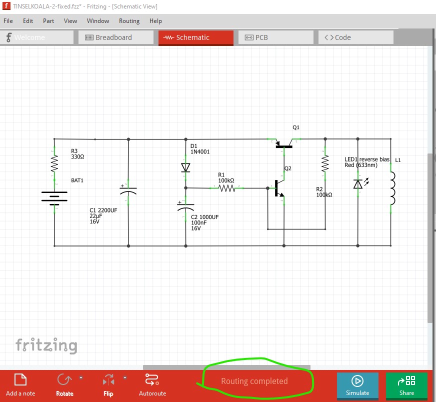
Peter
Peter,
Thanks so much! I can study this and hopefully learn something.