A simple work around for making a PCB would be to use 2 mystery parts set to double row and 4 pins.
If you want a custom part you could start with the mystery part set to double row and 16 pins. Then open it in the editor and save it as a new part. Then you would have to make changes to all the SVGs (with Inkscape or Illustrator), meta data and pin definitions. Making a new part is a lot of work for little advantage over using 2 mystery parts.
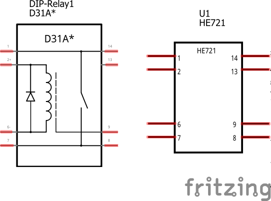
To make your own part I’d start from the dip-relay 1 in core parts which appears to be the correct package but possibly not the correct pin out. It is relatively easy to modify it if you supply the exact model of he721 you want since they come in several versions with different contacts.
The Op482 is an op amp. Both breadboard and schematic are wrong. You would be better off starting from the dip relay (search for dip-relay in core parts with the magnifying glass icon) which has the correct number and I think spacing of pins and a relay in schematic (rather than 4 op amps) …
The dip-relay 1 unfortunately have the wrong pin spacing both horizontally and vertically. The OP482 seems to be a much better match.
This is what I got after 30 mins of editing the OP482.
I’m not seeing your problem. Below are images of your part (which other than pcb looks reasonable) and the identical in package (but with a correct pcb and more detailed schematic) dip relay from core. Both are .3in wide (as is the data sheet for your relay) in breadboard but the schematic from core (with 0 effort) shows the relay coil and contacts in schematic. Your pcb appears to have a scaling problem and be incorrect according to the datasheet. It isn’t .3 in wide in a standard IC format as the relay is according to the supplied data sheet.
Thanks Peter for putting time and effort in helping a beginner
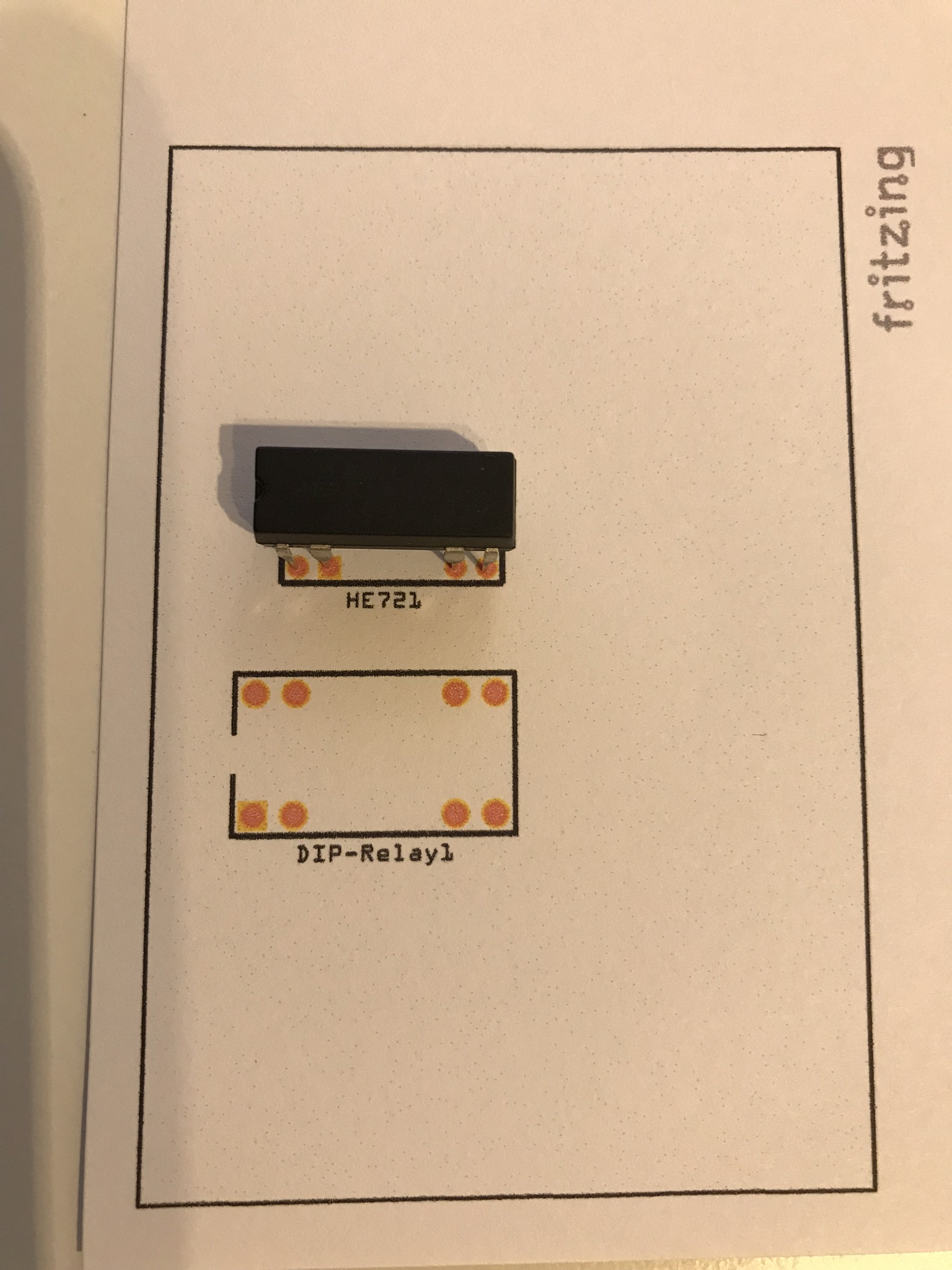
The D31A relay I had found before in fritzing app and even used that in my complete Thermostat design. Until I printed it the first time and tried to match components, then it was clear it had the wrong size and pin layout.
Exactly as your PCB image above shows the D31A is bigger, and that is what I see when printing as well and trying to fit a real HE721 to it, scale is off.
Maybe I’m doing something wrong (since I’m learning as I go along), but I guess the printed pcb needs to fit a real component for it to make sense?
Not a problem, folks here helped me when I was a beginner and it is in all our interest to encourage and help people make more parts. I owe you an apology because I didn’t look closely enough at the core dip part. It is in fact wrong in pcb view (and schematic as well for that matter). I’m fixing that up and will post a corrected part in a bit when I figure out what Inkscape is doing with the hole size in your pcb, your current hole size is way to big but the scaling is odd (not uncommon with Inkscape unfortunatly).
edit: OK, fixed that by my usual method: copy in a pad that is correct and change the current ones to match. In pcb I changed the square pad to pin 1 and changed the hole size from .041 to .035 (IC pin size), still much bigger than the recommended .024 in the data sheet. Schematic I swapped in the one from the dip relay and set it to be the same as one of the configurations. I didn’t bus the pins that are common (1 and 14 and 7 and 8) which should be done if this is the configuration you want. I fixed up some scaling issues in the original. In all three views I changed the pin numbers to start at 0, and in the fzp file removed the spice data for the op amp which no longer applies. In breadboard I added the breadboard layerId which was missing (the only thing I know that affects is exporting the part as an svg). So this part should do what you want with a correct pcb view. You may need to edit schematic if you want one of the different pin configurations.