I’m looking for the parts above. Unfortunately unable to find it. Could someone please point me in the right direction?
Thank you!
I’m looking for the parts above. Unfortunately unable to find it. Could someone please point me in the right direction?
Thank you!
It appears the motor driver doesn’t currently exist and thus will need to be made (which I will do.) The transducer has insufficient information to do anything with. There is no connector information available in the data sheet you supplied. We would need connection information to make a part and it isn’t present in the data sheet.
edit:
Here is the motor driver part. Note pcb view has been suppressed as not useful.
dfr0996.fzpz (30.9 KB)
Peter
Hi Peter,
Thank you very much for the Prompt response!
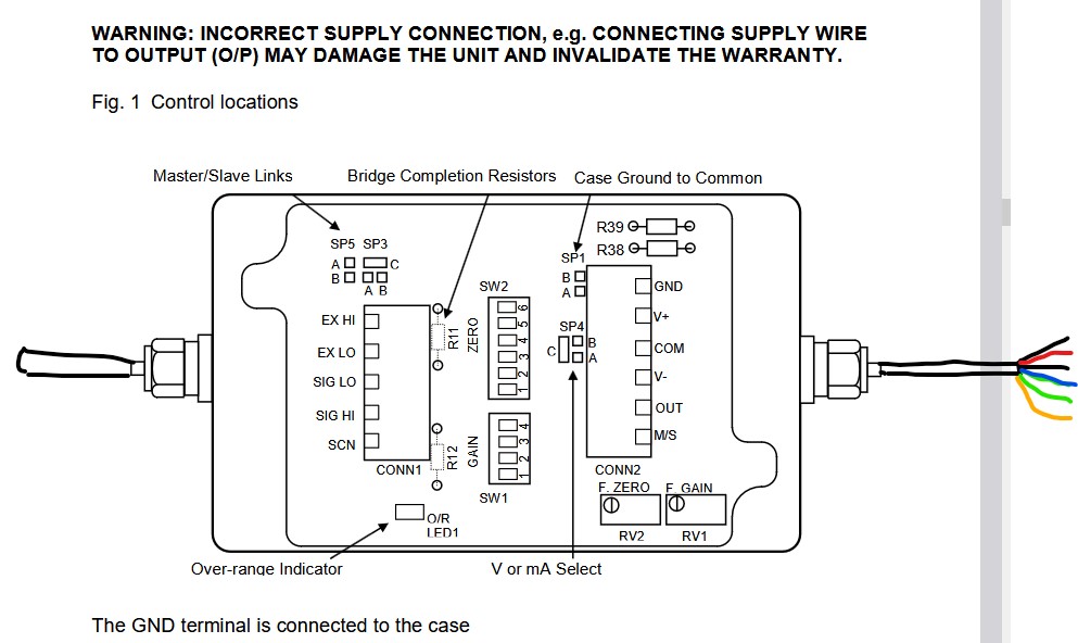
I just saw the schematic however its not able to do what I want it to do. I have uploaded in an image format of what im trying to replicate with the motor driver.
I have also found a pdf containing the details required for the LVDT by RDP.
Hope you can help. Thank you!
You will have to specify what you think is missing, as to me all required connections appear to be present in the part. It is intended to fit the other direction on the RPI (and will work if connected that way, although schematic will be somewhat messy) as is if you rotate the part 180 degrees and drag the part on to the RPI GPIO connector. Otherwise connecting wires as you indicate between the RPI and the part will also work. The connection information for the LVDT should enable a part to be made (I assume you want to connect it using option C for a voltage output which appears to be their preferred method although the connectors will work either way.)
Peter
Thank you very much!
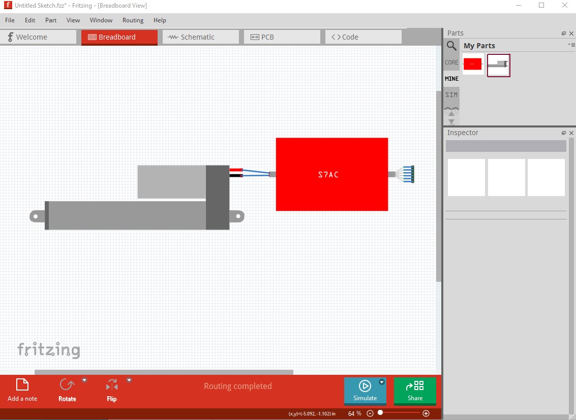
I assume the actuator is not needed here. It appears (although it is not clear from the documentation) that the actuator connects to the interface box on the left and you want the 6 wires from the interface to come out to wires with Fritzing connectors from the interface box like this
where the connections are on the colored wires on the right. There isn’t any indication of the physical size of the interface box so I guess just something reasonably small should do it. There is no apparent need of the actuator as Fritzing won’t care about it.
Peter
Here is a S7AC part.
S7AC.fzpz (3.1 KB)
assuming you want the linear actuator as well this part should do you
either one should do, here I used the linear actuator without pot.
the actuator has no connection in Fritzing to the S7AC part but will do for appearances in breadboard if required.
Peter
Thanks again for your help and for creating the initial part, I really appreciate it.
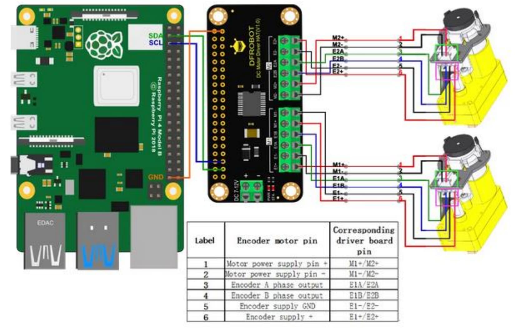
I’m currently trying to recreate a PWM-based proportional pressure control system for a Pneumatic Muscle Actuator (PMA) using a Raspberry Pi and the DFRobot DC Motor Driver HAT (DFR0592). The setup relies on using PWM output to drive solenoid valves, which regulate airflow into and out of the PMA.
That part you made in the image (the DFR Latching Relay) is excellent, however, what I’m trying to do now is model the DFR0592 Motor Driver HAT in Fritzing I need a custom part for it that has:
I’m not trying to use it to control motors, I’m using the PWM outputs to drive two solenoid valves (one for inlet air and one for exhaust), effectively controlling the contraction of the PMA.
I want to recreate this setup in Fritzing for documentation and layout planning. My challenge is that I haven’t found any part that mimics the actual pin layout and functionality of the DFR0592, especially one that works nicely in breadboard view and lets me place it over the Pi GPIO header as a HAT.
Would you be able to help with building that part if possible?
Thanks again for your time and support, and for all the great work you’ve already done!
Best regards
The motor driver part posted has all the connections that you list. If aligned properly it should fit on the RPI GPIO connector (and depending on how the CPU board is configured) connect. I am not seeing your problem here.
Peter