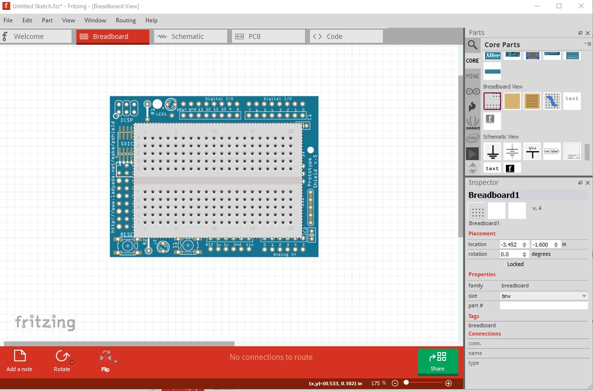
I am trying to find an Arduino UNO Proto-shield library part that allows putting a breadboard ON TOP of the proto-shield - i.e. that the proto-shield board part respects the “Bring to Front” and “Send to Back” commands with respect to a white “mini” breadboard. The existing proto shields from the SparkFun and Adafruit libraries do not seem to allow this.
However, I distinctly remember having an older installation (on an older PC), that included an Adafruit proto shield, and I think it had a version number, something like “v.5”. I remember being able to put a breadboard on top of that protoshield board (in Fritzing’s Breadboard view).
I do not recall if I obtained the a library part that could do that directly, as I received it, or if I did some modification to the part, to allow the proto-shield board to go behind the mini breadboard.
Can someone please help me out with this? I need either a link to a UNO protoshield board that can be placed behind a breadboard, or instructions on how to modify an existing protoshield board part to allow it to be placed behind the breadboard.
The reason for the 0.9.6 restriction is that I believe breadboards are always supposed to be on the bottom and not movable, but in 0.9.6 (at least) that doesn’t seen to be true. I can make the breadboard on top. I’m not sure if this is 0.9.6 specific or I misunderstood breadboards.
edit: Learned something new again! The trick here is this part has a breadboard layerId of breadboardbreadboard rather than the standard breadboard. With the layerId set to breadboardbreadboard the part can be moved up and down relative to the breadboard (changing the layerId to breadboard makes it act like a normal part and it won’t go below the breadboard!)
Thank you so much, @vanepp. I guess I was using the wrong search terms or something; I just could not seem to find it earlier today. Now that I have seen the forum thread again, I also remember dendoracing’s avatar/icon.
@vanepp : Just read your “Edit” comment. So what series of steps do I need to perform to change a part layer ID (i.e. from “breadboard” to “breadboardbreadboard”)?
I am not (yet ; ) familiar with editing Fritzing parts.
Thanks again.
DuinoSoar
Edit: So I tried using the “Edit Part (new parts editor)…” command and opened the parts editor on the shield created by “dendoracing”. I could not find anything in there called “layerid” nor anything set to “breadboardbreadboard”. What am I missing?
Edit2: The reason I ask is because I would REALLY like to use the “Adafruit Proto Shield R3” (the blue one) in the same manner, if easily possible. It looks more realistic (with the header sockets, buttons, LEDs, etc.) than the green “v.5” part. Is there some way I can get a mini breadboard to appear on top of it by simply changing a parameter or two in the parts editor? (Or by editing a file or something?)
(the breadboardbreadboard needs to match text and case with the layerId in the fzp file.) Then rezip the .fzp and 3 .svg files in to a .fzpz file. If you use Inkscape or another svg editor you are best to run the result through FritzingCheckPart.py to clear some of the changes that the svg editors make that Fritzing doesn’t like. The text edit won’t change anything except the layerId.
@vanepp : Thank you, Peter. The green “v5” part is already set up as a breadboard - it is the the blue “R3” part from the Adafruit Arduino library that I want to try to change, but I do get your meaning. (BTW, I am familiar with XML files.)
But I notice that “dendoracing” defined all of the connector elements as also being in the “breadboardbreadboard” layer. Would I also need to do that for the Adafruit R3 part? (BTW, the file name for the Adafruit Arduino library part (the blue “R3” part) has a long hexadecimal string in the name; I found it by doing a content search for “Proto Shield R3”.)
BTW, Peter, I really do appreciate your help on this. Thanks.
The breadboardbreadboard (or breadboard) layer should be the entire svg. I often ungroup the whole svg then do an Edit->select all and group then rename the resulting group to the layerId (usually breadboard, but breadboardbreadboard in this case.) If the layerId is missing in the svgs (any of them( the part won’t export as an image (svg, pdf, jpg etc) but that is the only problem I know of. The layerId in the .fzp file is the one that the code uses to decide if this should be a breadboard or not. So yes that should be done for the new board too but as noted the fzp file is what controls how the part acts in breadboard view.
The hex value is from parts editor because the moduleId must be unique so it generates a hash based at least partly on time that will be unique. It is usually (but not always) stripped off when parts are added to core.
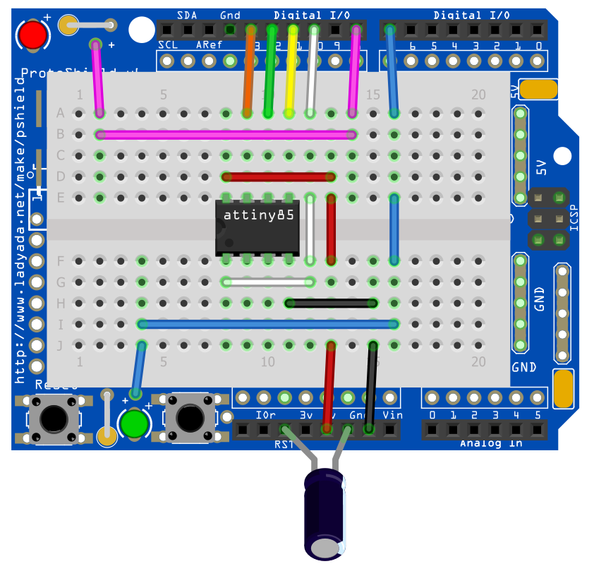
It probably could have been on a “mini” breadboard but the “tiny” works okay.
So I edited the Proto Shield R3 .fzp file with a text editor, to change the XML “layerid” attribute (line 36) and all “layer” attributes (some 380 lines - the editor’s “replace all” feature is VERY handy ) from “breadboard” to “breadboardbreadboard”. These attributes were not specified in the XML for any of the .svg files associated with the Proto Shield R3, so I did not change those.
FYI, this programmer would use the ArduinoISP example sketch with OLD_STYLE_WIRING defined (and ARDUINO_HOODLOADER2 NOT defined). The top (red) LED is the error indicator, and the bottom (green) LED is the “programming” indicator. (No heartbeat LED, but one could be added onto the breadboard if desired.)
Caveat emptor: I have not tested this (yet).
Edit: Sorry. I should have written that the .svg files had lots of <g> tags with the id= attribute, but none had an id set to “breadboard.” So I did not change the .svg files.
 ).
).


 )
)