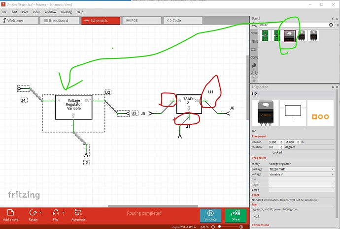
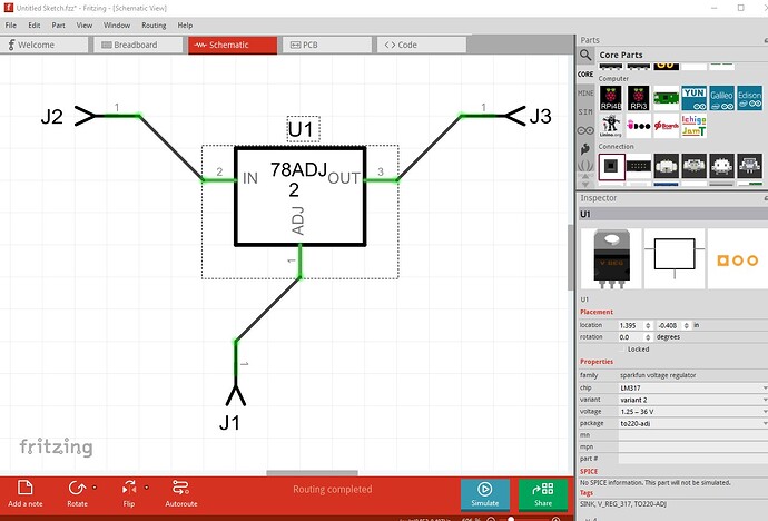
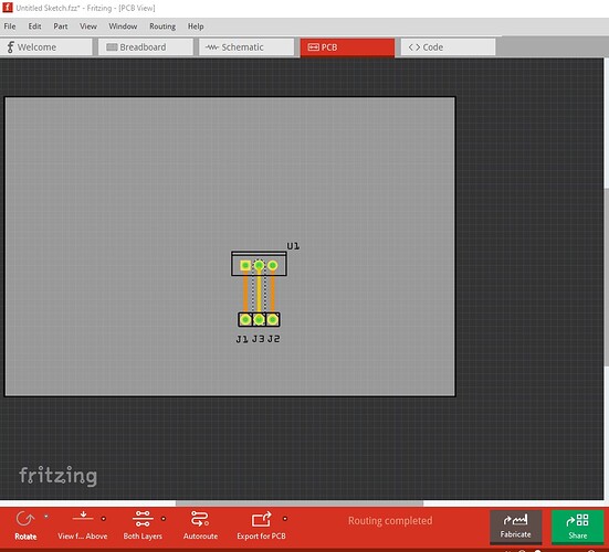
A couple of problems (not unusual, parts creation is complex!) The part on the left is a sparkfun LM317 the one on the right is your new part.
FritzingCheckPart.py (which checks for errors in parts) flags these errors (among others, these are the important ones here)
Error 77: File
‘svg.schematic.prefix0000LM317A_9e3c2406a5af192c0c2f6ece196bf3bc_1_schematic.svg.bak’
At line 19
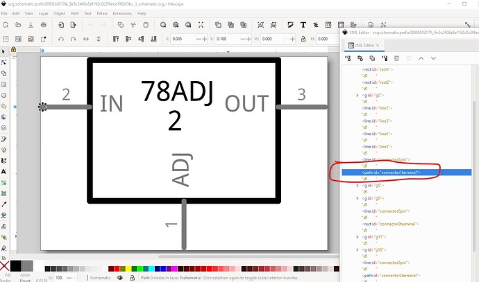
terminalId connector1terminal can’t be a path as it won’t work.
Modified 2: File
‘svg.schematic.prefix0000LM317A_9e3c2406a5af192c0c2f6ece196bf3bc_1_schematic.svg.bak’
At line 27
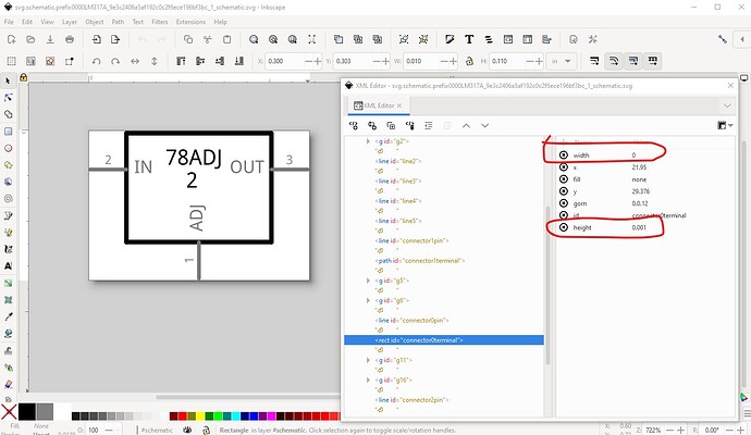
Connector connector0terminal had a zero width, set to 10
Check the alignment of this pin in the svg!
Error 77: File
‘svg.schematic.prefix0000LM317A_9e3c2406a5af192c0c2f6ece196bf3bc_1_schematic.svg.bak’
At line 51
terminalId connector2terminal can’t be a path as it won’t work.
Error 66: File
svg.pcb.prefix0000LM317A_9e3c2406a5af192c0c2f6ece196bf3bc_1_pcb.svg.bak
At line 13
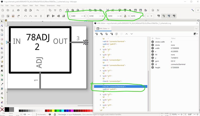
the error indicates that it will affect Fritzing operation (which as we see it does!) The fix is fairly simple. Edit the schematic svg in Inkscape and we see that connector0terminal while present is a path which won’t work. As a result the wire connection is in the center of the pin and thus offset 0.05in from the grid which is incorrect.
connector0terminal is correctly a rectangle but has a zero width (circled in red) and thus neither Inkscape nor Fritzing will accept it.
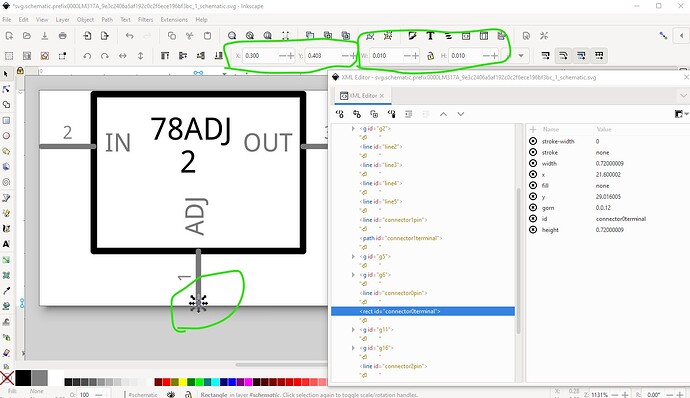
connector2terminal is a path again and thus doesn’t work. To fix this I added a stroke (set to none) and a stroke-width of 0 to the rectangle, then set the height and width to 0.01in in the tool bar at the top. That creates a rectangle of the same width as the pin. Then I moved its x and y coords to be the end of the pin. Now duplicate that rectangle, and move it to the other two terminalIds that are paths, set the correct x/y coods to the end of the pin and rename the rectangle to the correct terminalId and the problem is fixed.
do the same for the last terminalId
Save the svg as a plain svg and recreate the part and it should work. Now for the errors in pcb.
Error 66: File
svg.pcb.prefix0000LM317A_9e3c2406a5af192c0c2f6ece196bf3bc_1_pcb.svg.bak
At line 15
Connector connector2pad is a duplicate (and should be unique)
Error 66: File
svg.pcb.prefix0000LM317A_9e3c2406a5af192c0c2f6ece196bf3bc_1_pcb.svg.bak
At line 16
Connector connector1pad is a duplicate (and should be unique)
they may not matter much because they will probably be ignored, but it is better to fix them.
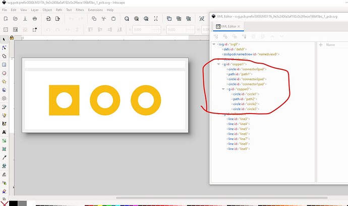
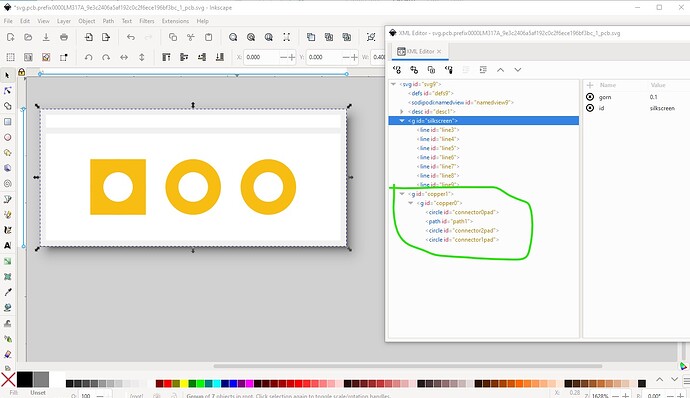
I’m not sure why it is reporting a duplicate because it doesn’t appear to be, but it is an older format that should be updated. Currently copper0 should be a child of copper1 and the connections should be in copper0 like this:
So save the pcb svg and remake the part. Run it through FritzingCheckPart.py and it has some warnings but no errors so try the new part and see.
and indeed things are now correct.
Here is the fixed part (I didn’t change the moduleId so you will need to delete the original part from your mine parts bin to load this one!)
Voltage Regulator-fixed.fzpz (6.8 KB)
Everything I did here and a reference to FritzingCheckPart.py is available in this tutorial set:
Hope this helps! If not feel free to ask for clarification.
Peter
