Hello everybody,
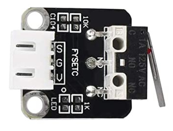
Do any of you have already made a limit switch like this one? If yes, could you please share the file?
Hello everybody,
Do any of you have already made a limit switch like this one? If yes, could you please share the file?
Are you still looking for this part?
I’ve made a quick, basic breadboard view for the part.
The part wouldn’t be hard to create, but I need some details to do that. Do you have a datasheet for this part? What are the pin-outs for the connector?
I can finish this part if you still need it and can provide some info about it… just let me know…
Randy
Do you need the Switch part or the Module?
Hi!
Thanks for the answer. Unfortunately i couldnt find any datasheet of the part, but i believe this board is very simple and from the pictures (from the link I sent above) we can see that it has a resistor as a pull-up, a small capacitor probably for voltage atenuation, plus an LED + resistor…Thats basically it.
Pins are 5V, 0V and Signal.
Let me know if this is enough…again thanks very much for the help !!
im looking for the module.
Give a Picture captured by you, the site image has some multiple/mirror images…
And give the board size, Screw Hole Spacing etc…
so @just_randy can complete the part…
Measuring mine while still on the Ender3, it’s a 20x20mm PCB with holes at 15mm spacing, ie 2.5 mm in from the bottom and sides. Holes I’m guessing are 3.5mm, or at least something bigger than the M3 screws it has.
Helpful, but not enough information. 5V - is that the V pin in your picture? 0V - I would assume is ground, or common. Signal I assume is the S pin?
The part appears to be nothing more than a mount for a switch. The switch has 3 contacts, C- common, NO - normally open, NC - normally closed. So which of those pins are the S, G, V, pins? I kinda need to know that for the schematic symbol.
The PCB version of this part will just be a silkscreen, since the part can’t be soldered to a PCB, there will be no copper pads/holes.
So I’m curious as to why you want this part. You see, I make my own parts because I need the PCB portion of the part. I need the PCB layout (silkscreens and pads) for having PCB’s made. Since this part won’t mount on a PCB board, why do you need the part instead of using a simple switch?
Randy
My Ender3 goes S G V on the JST the same as the top pic, so I guess it’s Signal, GND, V+. The 0 is probably the LED polarisation.
@Old_Grey - thanks for your help!
Here’s what I’m not understanding…
This part is nothing more than a switch with some supporting components, so basically, it’s a switch. Here’s my schematic symbol for the part (taken from a core part):
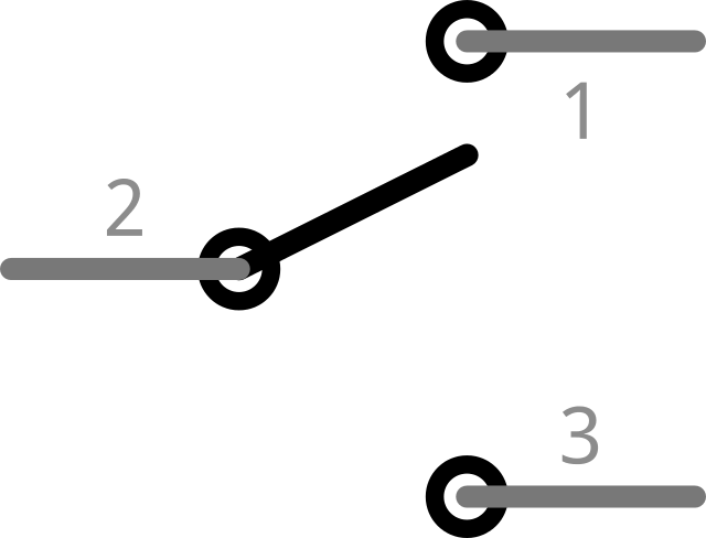
3 pins - numbered 1, 2, 3, which of those pins are S, G, V? So is pin 2 on the schematic S, or G, or V?
I just don’t know what pins of the schematic should connect to what pins in the breadboard view.
Randy
While I’m not @Old_Grey, the pin id (of the form connector0pin) in breadboard needs to match a pin in schematic called connector0pin that is in the same place as the pin in breadboard and pcb. The S, G and V are likely labels on the pins in breadboard and Fritzing doesn’t care about them. It cares that connector0pin (which will be on the pin labeled S, G or V) in breadboard is in the same place connector0pin in schematic and pcb are. So in the breadboard svg, you need to figure out what connector number is associated with the pin that the S, G or V label is associated with and match that with the corresponding pin in schematic.
Peter
Sorry wasn’t thinking, and still not 
I just buzzed them out and it looks like the 3 micro switch pins connect directly with the JST pins, so S goes to C on the switch, which I assume is common - probably your #2 -, G to NO which has no continuity when at rest but buzzes when the switch is pressed - probably #3 -, and V goes to NC which buzzes until the switch is pressed - probably #1 -.
Yep, that is what I am trying to figure out, and thanks to @Old_Grey, I have an answer.
The part is attached to this post, but someone should run it through the parts checker script to make sure I didn’t miss anything. Anyone who runs this thru the parts checker will find errors in the PCB because there is nothing in the copper groups in the .svg file, it’s just a silkscreen. If there are any serious errors, let me know and i will fix them.
Randy
Limit Switch.fzpz (11.0 KB)
Hi, @just_randy. Thanks for the part. Sorry for bumping this thread.
Two of the pins are labeled as G: NO and S: Common. Shouldn’t those descriptions be swapped?
Doesn’t look like it (I don’t see much info on the switch on the net though.) V appears to be +V voltage (NC) which with the lever not tripped will put +V on the S (signal/common) pin and when the switch trips S will change to ground to indicate the limit has been reached. So the part looks correct.
Peter
Ok, I think I understand. Thanks, @vanepp!
@fepegar - Sorry to not get back to you. When I first saw your post, I didn’t have time to reply, then later on, I forgot to reply.
I created this part only to strengthen my parts creation skills. If you read thru this thread, you’ll see the OP stopped responding to my questions, maybe because they couldn’t answer my questions about the connectors. Old_Grey did have one of these switches and measured for continuity between the connectors. My part was created based upon his readings.
Somewhere there could be an error, or misunderstanding.
I can fix the part if needed, and anyone can edit the part as they see fit.
Randy
Thanks, @just_randy. I hadn’t seen the OP’s photo of the switch ![]() . Of course the pins are coherent with the photo. I suppose I found S-G-V confusing and arbitrary, compared to C-NO-NC. But that’s of course the manufacturer’s “fault” (or my lack of experience). It’s the first time I work with limit switches, and I hadn’t touched electronics since 2010. The goal is to control a claw crane with Arduino.
. Of course the pins are coherent with the photo. I suppose I found S-G-V confusing and arbitrary, compared to C-NO-NC. But that’s of course the manufacturer’s “fault” (or my lack of experience). It’s the first time I work with limit switches, and I hadn’t touched electronics since 2010. The goal is to control a claw crane with Arduino.
Anyway, thank you both for your answers!