I am placing a dozen or so LEDs, SMD type 0805, on my board. I noticed that the PCB view doesn’t indicate the anode (+) from the cathode (-). What do people do on their boards to indicate this? I though about putting a text symbol in Silkscreen, but is there a standard practice?
For the standard led when I select the 805 [SMD] package in inspector there is a black line on silkscreen that indicates the cathode. Which led part are you using?
Yep, there usually isn’t much space to do things on silkscreen with smd parts so subtle is usually the rule . As well parts are user created so sometimes things like pin 1 indicator are entirely missing.
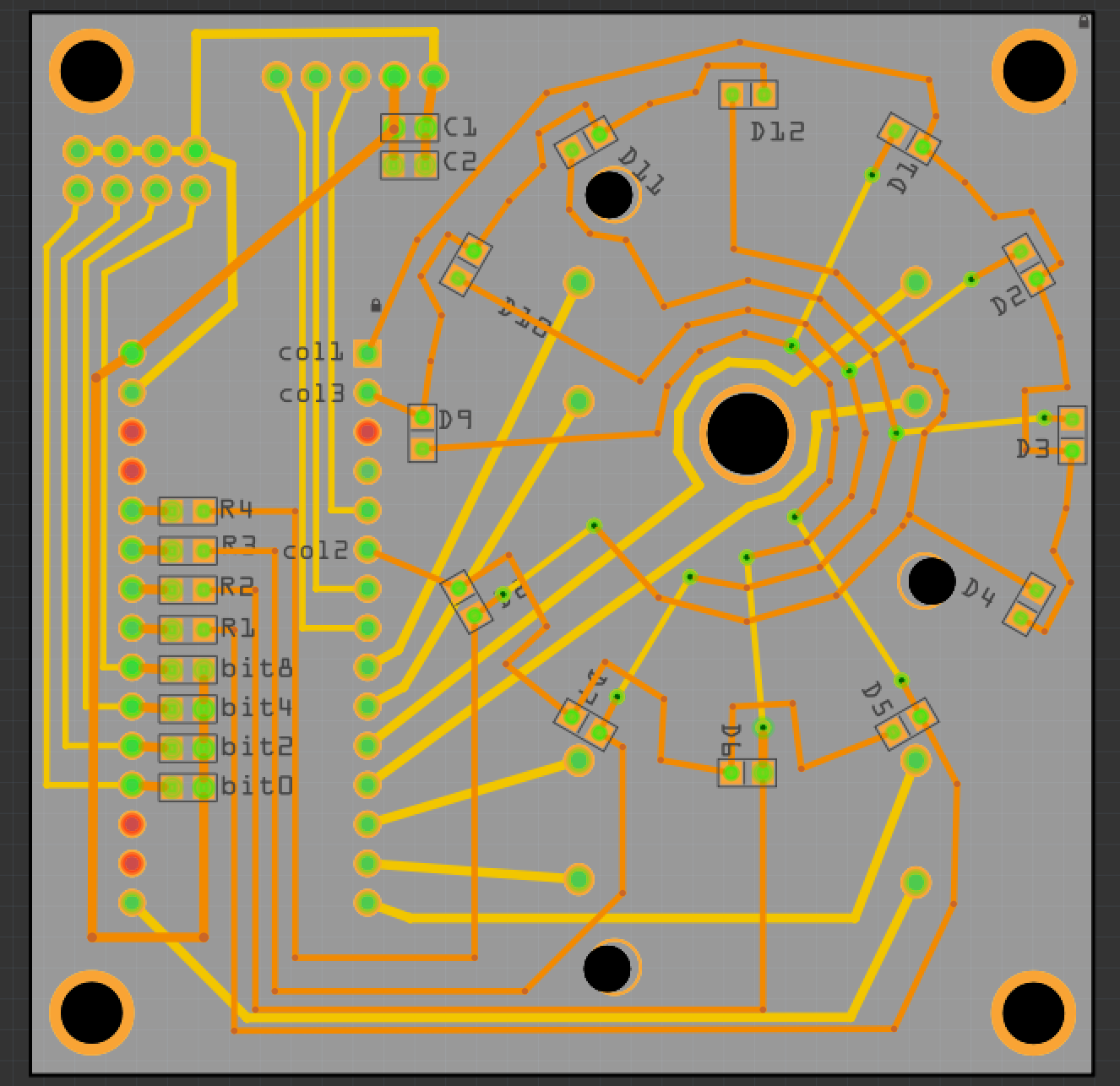
I’ll straighten out my led labels (D1…D12) – puitting them always closest to the cathode – to enforce that.
This is the bottom of the board (although user-visible), so it is relatively uncluttered.
Yeah it is quite normal and for the assembly you’d better design the silkscreen on the pcb boards to indicate.Why not just design in the silkscreen - close to the cathode (or + close to the anode). It would be clear enough.What do you think?