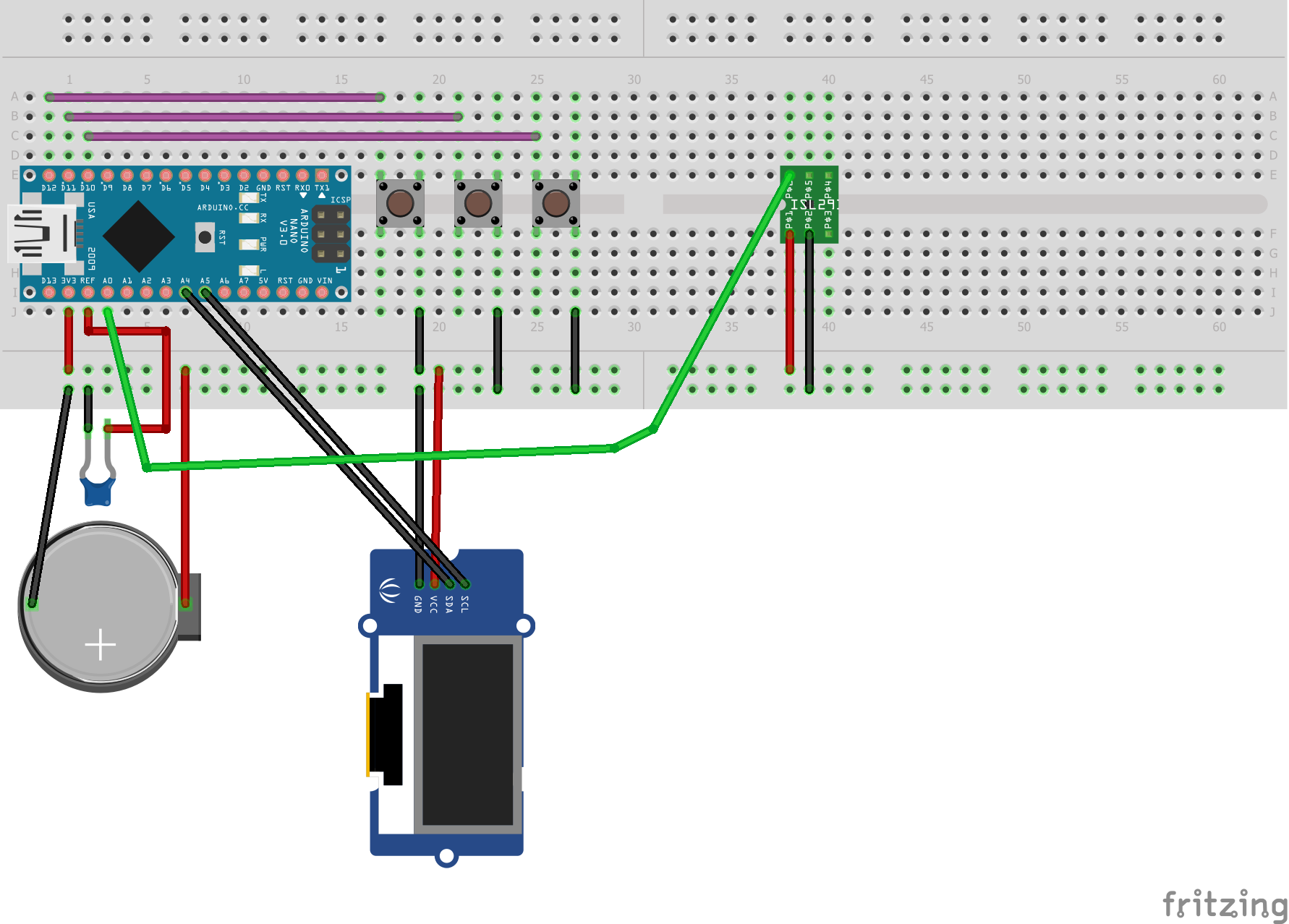
Other than there likely isn’t a part for the sensor (although it would be easy to make one from the generic part) if you enter your (presumably working) breadboard layout in to breadboard view in Fritzing it will create most of the schematic for you with rats nest lines indicating where the wires go. I made an OLED part for someone a while back and at least the company name (may or may not be the same model) is familiar. However I’m going to guess that your circuit doesn’t work because you don’t actually appear to have a reference voltage just a capacitor (which will effectively give a reference voltage of 0 unless you are using the internal reference). There likely needs to be a connection from the ref connector to the 3.3 volt rail to actually get a reference (and then you likely have noise problems as he indicated). For really good results you would need a higher voltage battery feeding a 3.3V regulator and an external voltage reference chip to give you a clean reference voltage.
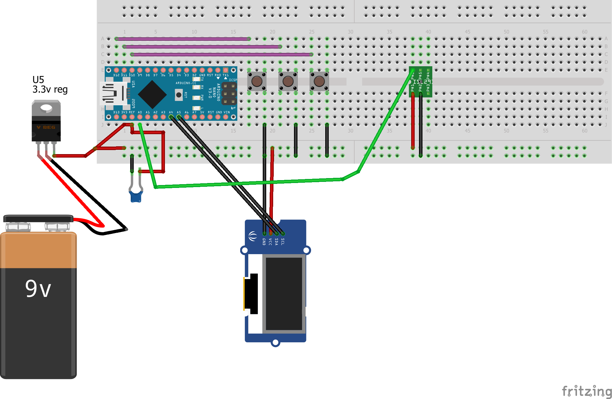
This is probably a better bet although I’d probably replace the 3.3 regulator with a cheap ($2 - $3 from ebay) buck regulator such as this (the first one I found in a search for buck regulator on ebay).
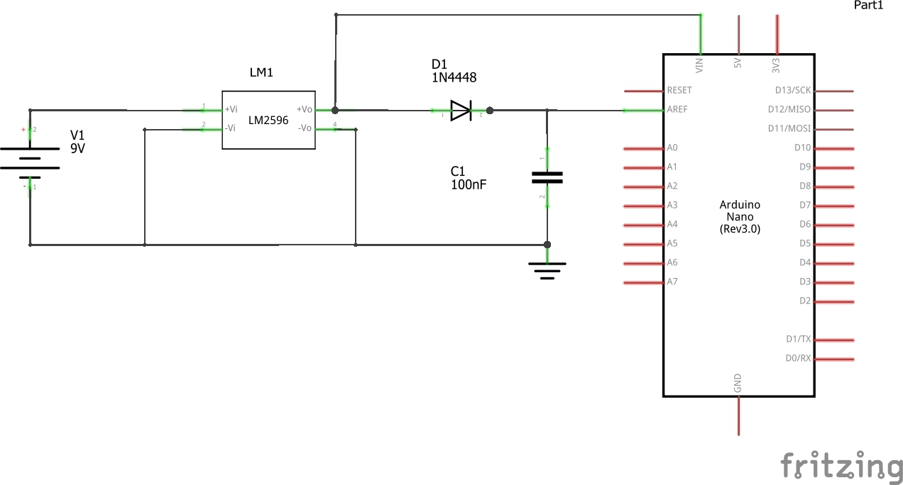
Adjust the output voltage with the pot to 3.3V (note these have a quirk, I thought mine were broken til I saw a post that said the pot only works across about %25 of its rotation, so try it at both extremes of pot rotation before concluding it doesn’t work ). The reason for this against the simpler linear regulator is battery life. The buck regulator is about %90 efficient in converting the 9V to 3.3 where the linear regulator is somewhere less than %20 efficient (it is dissipating 6V as heat to get to 3.3V). For the reference voltage I’d try this circuit:
The 1n4448 diode will drop the reference voltage by about .7 volts (a 1n34 germanium diode would be better but is less common ) and the capacitor on the end of the diode should then filter the reference voltage to a stable value and block the supply ripple from depleting it. Note the “should” in the above as I haven’t actually tried this . To test do the same thing he did to show the ripple effect: short the analog input pin where the light sensori connects to ground instead of the sensor and display the values on the oled screen without the diode and capacitor you will probably see the ripple that he saw, with the diode and cap you should see 0 as he did with his lab supply connected.
Hi…i am a new user here. In my case i made an OLED part for someone a while back and at least the company name is familiar. However I’m going to guess that your circuit doesn’t work because you don’t actually appear to have a reference voltage just a capacitor.
 ). The reason for this against the simpler linear regulator is battery life. The buck regulator is about %90 efficient in converting the 9V to 3.3 where the linear regulator is somewhere less than %20 efficient (it is dissipating 6V as heat to get to 3.3V). For the reference voltage I’d try this circuit: