New here. Just getting into this stuff and I’ve bungled my way through tutorials on Adafruit and I’m now gearing up for the project I started learning this for. I’ve gotten to the step of hooking/soldering everything together and made a diagram in fritzing. I could use some help/verification that I’m barking up the right tree and doing things correctly.
I’m attempting to make a model interactable/light up. Google Forgeworld Warbringer Nemesis to see the model in question(Since I’m limited on images & links apparently).
So the idea is to light the body/torso of the model with roughly 6 LEDs and have each arm lit with at least one LED, or in the case of the gatling gun, have the servo hooked up so it can spin. Each gun/arm should have detachable connectors so other weapons can be swapped in.
I’m planning on placing capacitive touch points all over the model to control the state of different parts. I’m going to try the conductive paint to see how it works and if it doesn’t I’ve bought some copper tape.
I’ve mostly prepped the model. Now I’m working on the wiring so I can test the setup before gluing everything in place and painting.
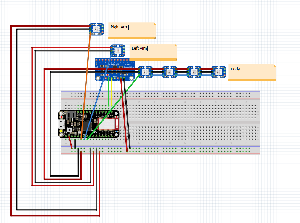
Here is the Diagram and project file. Not sure I’ve done what is necessary and I’m still learning terms. I have not added in the servo, but the intention is to make it so either arm can swap to it.
Welcome aboard, it looks like you have made a common mistake and made connections schematic before completing breadboard. Unlike most other eda programs Fritzing propagates changes between views, and creating a short in one view can sometimes make changes that can’t be backed easily. The indication of problems is in breadboard view here:
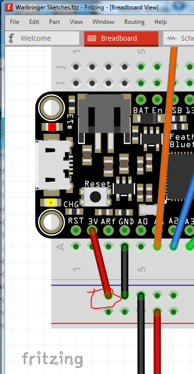
The dotted lines circled in red indicate connections that haven’t been made yet. As does the message circled in blue stating that two nets remain to be routed (the two circled in red.) The problem is that SCL should not be shorted to SDA, and ground should not (very likely anyway) connect to VIN but rather to GND two pins to the right and the red wire should go to Vin with no connection to 3V0. In addition there is a short from GND to 3.3V here:
The red wire should be to the bottom connection on the breadboard not ground. Your problem looks to have partly happened in schematic which currently looks like this:
The black lines and the 2 of 8 nets routed at the bottom indicate that connections have been made in this view (and thus will reflect in to breadboard and pcb views.) but they are likely incorrect. Part of the problem is that Fritzing positions parts on top of each other when placing them so if I separate out the parts, schematic actually looks like this:
the four red circles show where there are connections that shouldn’t exist. While I can delete them in schematic, that doesn’t fix the problem because the shorts have corrupted the routing data base and it looks to be unrecoverable. Unfortunately what you need to do is start a new sketch and redo the entire breadboard view (making the corrections noted.) Once that is done you can then move the parts in schematic around (using right click rotate to rotate them in to the correct position, or drag the part in to schematic first as it will then usually be correctly oriented) and then click on each rats nest line to make the connection then drag the connection to an appropriate place and all should be well.