Thank you for your feedback!
I did raise additional questions in my head.
From what I read, I got the impression that for all three views the part dimensions should mirror the real dimensions. So would you say that this is not necessary for the schematic SVG, and that the schematic part should just be large enough to host all the pins and necessary information?
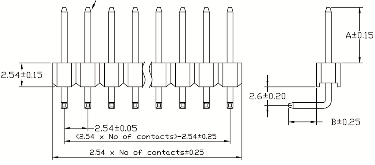
I used the real dimensions and then wanted to put the top and bottom pins in the middle, so it ends up not being a multiple of 0.1 inch from the other three pins. From how I understand your comment, I should rather have the whole part adhere to the 0.1 inch grid in the schematic SVG, as it will also move on such a grid in Fritzing’s schematic view. Hmm, but the pin’s length is 0.1 inch, isn’t it? I thought I had that right.
Yes. That is what I measured. And it also fits with standard right-angled pin headers, I found.
That sounds like a good idea.
Yes. I did not put any in the SVG after I read that they are optional and Fritzing will simply assign snap points itself. But they showed up in the .fzp file. And this is where the weird behaviour of Fritzing begins, or, at least behaviour I do not understand, yet.
Which makes me wonder, do you guys write the .fzp part files by hand, instead of using the Part Editor. I did the SVGs in Inkscape and then used the Part Editor. (To be honest, I don’t know why people keep saying that is complicated, I found that part easy. But maybe I haven’t done anything complex, yet.) What I also did, was start with an existing part (the core rotary encoder) as all tutorials I found, said, that is the only way. By now I am not convinced anymore, that that is a sane way to go.
I have the suspicion that a few irritating quirks I encountered stem from basing my “new” part on the original encoder. I may be wrong. But the terminal ids in the .fzp file may be caused by that.
So, what do you pro’s do, start from scratch and hand craft all XML files?
Doh! You are right. And there I was, thinking that I had tested my part. I guess I should have read “Part 4: Testing” of the tutorial first. I now realise I only tested the breadboard view thoroughly, not the others. My bad. Thanks for pointing that out.
I did run the FritzingCheckPart before posting. Truth be told, I mostly ignored the output. I am not too enamoured with that tool for a few reasons. But yes, it did point out the terminal ids, I just thought that the part editor might not care or even be right, so I didn’t act on it.
So all in all, I feel I should give this a second try and start the part from scratch, with more manual XML file editing.
Thanks!