Please help me create this thing as a fritzing part for a school project.
Part in SVG format:

Type
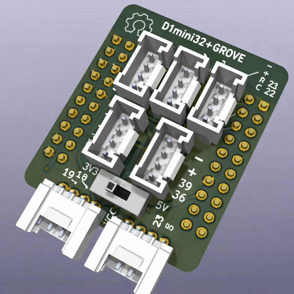
Breakout board, sub assembly, plug in module (A)
Please help me create this thing as a fritzing part for a school project.
Part in SVG format:
Type
Breakout board, sub assembly, plug in module (A)
@frederik-dude Why did you happily ignore the template? The link section? What is this even
(Sorry if ping was not needed)
For following reasons:
**Name of the part❗: It does not have a name yet
Your previous work, similar parts: I have not found similar parts, and have no previous work making parts
Top view❗: I was only able to attach one image on this post because I am a beginner
Datasheet❗
The official documentation of the part manufacture is linked here:
Please add a link to PDF of the manufacturers datasheet: None exsists, I am the manufacturers.
Footprint: I assume it did not apply here.
Please excuse me if any of this sounds rude, english is not my first language.
Oh so you want a sketch not a part. Ok (btw you can ask in your native language.)
Yes, I would like help on how to make a sketch for a part in fritzing.
You do not really make a sketch for a part.
A part comprises typically of an icon, a pcb view, a schematic view and a breadboard view. Each of them is an SVG file and the part file combines those SVGs and a description/property part, the FZP file.
If you take an fzpz file and rename it to a zip file (example.fzpz => example.zip) then you can unzip the file and see all the files contained.
but then how can this part appear in schematic view? I would like to use it so I display how it would work. I can send an image to show it should look like.
Hi @frederik-dude I don’t quite understand what you mean. Can you explain in your native language
A (finished) sketch is multiple parts with connection between them, in 3 separate views. Breadboard, Schematic, PCB. A full part is 3 (or 4) separate SVG files, one for each of those views (plus icon), plus a special format (XML) file that contains additional information about how that part (connector) behaves internally, and what is used in each of the views. The SVG files need to have some information about the connectors, so that Fritzing can managing the wiring.
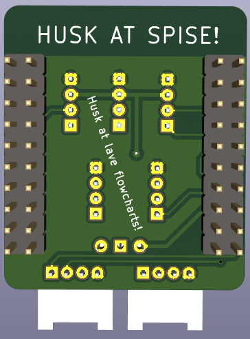
Your original image looks more like a Schematic view of a sketch than a part. A part for a breakout board does not show all of the wiring connections, or individual parts that make up the board. It is just a block with the external connectors for the board (on schematic view). PCB view has a footprint for how the part would be connected to a pcb board. That view is usually suppressed for most breakout boards, because they are not intended to be soldered on to a pcb.
Definitely. It cannot harm to see.
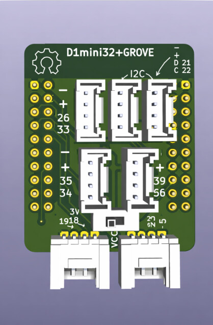
Did you render this part? If so, can you render at 90 degree viewing angle?
@real-bombinho
did this help?
Yes, I will have a look at it when I get a bit more time at my hands. Looks good.
@real-bombinho sorry to bother, but did you look at it?
@real-bombinho sorry to bother, but when do you expect you might be able to have it done?
Sorry @frederik-dude , I was not getting as much time as I was hoping for,
I just throw in what I had made earlier
It might be useful as an icon but there is no scale and certain bits are still sticking raw together.
Unfortunately a few other things have taken preference currently.
I would like to create a part in Fritzing that I can use to illustrate how a circuit should work.