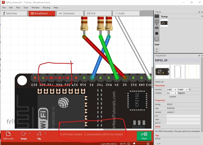
Looks to be operator error. You have miswired schematic compared to breadboard.
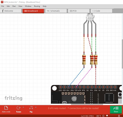
breadboard has unintended rats nest lines (likely reflected from schematic) and unrouted nets (because there are rats nest lines from schematic that are not routed.) To fix this I selected in breadboard view Routing->Select all wires then hit the delete key to delete all the wires in breadboard. That produces this (which is the connections in schematic reflected as rats nest lines in to breadboard.)
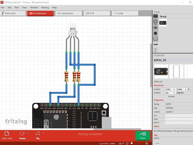
As you see it doesn’t look much like the original picture. Clicking on and routing the wires produces this which should be a representation of schematic (although it doesn’t look much like it!)
so now switch to schematic and do the same thing to delete all the wires.
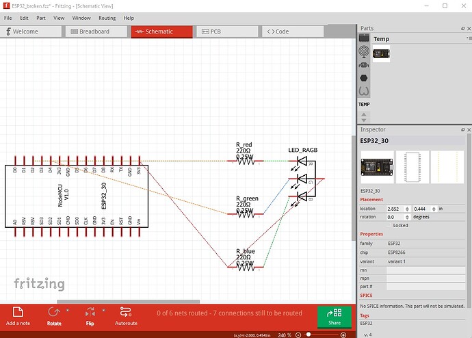
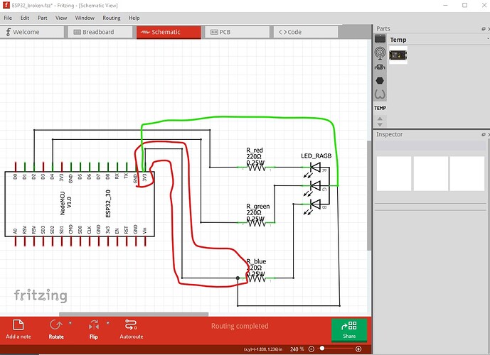
then click on the rats nest lines to connect the pins which results in this
The wire to the resistor (circled in red) is presumably wrong. It should connect to a digital I/O pin not 3.3V. As it stands the blue LED will never light because it is connected to 3.3V instead of a digital I/O pin. You are best to make all connections in one view then click on the rats nest lines in the other 2 views to make the associated connections (and correct them if they are wrong in the original view!)
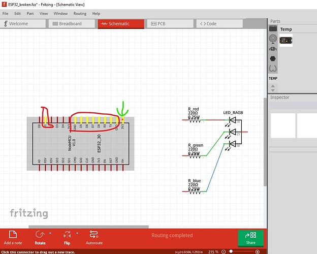
With all that said, it looks like the real problem is that the node mcu part is broken. Here I disconnected all the wires from the node MCU and then left clicked on the 3.3V pin. All pins that are bussed together light up yellow (which is way to many pins indicating the part is broken!)
only the 3.3V pin with the green arrow should be lit yellow. You need to find a better Node mcu part than the one you used. There are lots of them around (a google search of the form (“fritzing part esp32 node mcu” should find a bunch) then you need to check and make sure the part actually works correctly and matches the cpu board you have (clicking on the pins and making sure only identical pins such as GND or 3.3V light yellow is a good start) and go from there.
edit:
I started to check the part, and when I did that I discovered I had already seen it. The corrected version is here
you can replace the current one by doing a delete minus of the part. That will delete the part but leave the wires. You then need to load the fixed one, move it in the sketch and then drag the wires to the new part to connect them.
Peter
