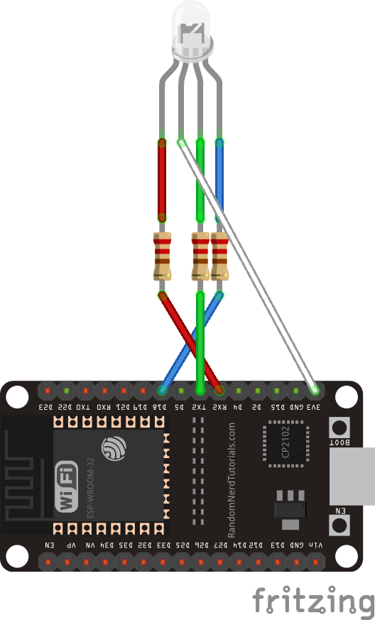
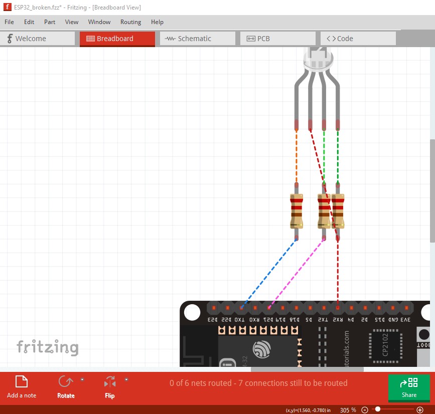
Setting up a few sensors (BME280, BH1750 and AM312) together with an RGB LED (common anode) plus 3 resistors connected to an ESP32/30pin in breadboard view - switched over to circuit view and wondered about suggested wiring. Set up a new breadboard with LED / resistors only connected to the ESP32 - same weird wiring suggested.
…
What I expected should have happened instead:
R, G and B should connect to Pins RX2, TX2 and D18, anode should connect to 3V3.
…
My version of Fritzing and my operating system:
0.9.4 and Win10
(Actually I can’t find my paid download and don’t want to pay again right now.)
…
Please also attach any files that help explaining this problem
Upload the sketch file (the .fzz file, upload is 7th icon from the left in the reply menu) and one of us will have a look at the sketch and tell you what is wrong. Without the sketch it is too much work to try and reproduce.
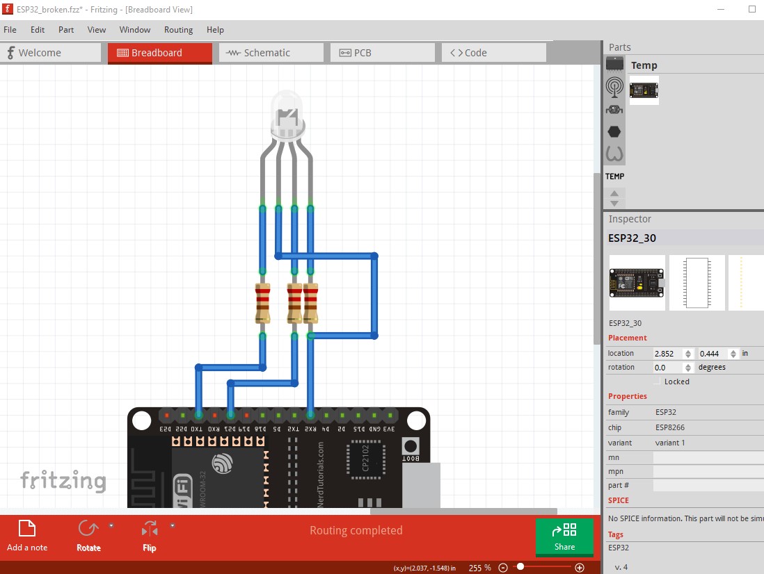
breadboard has unintended rats nest lines (likely reflected from schematic) and unrouted nets (because there are rats nest lines from schematic that are not routed.) To fix this I selected in breadboard view Routing->Select all wires then hit the delete key to delete all the wires in breadboard. That produces this (which is the connections in schematic reflected as rats nest lines in to breadboard.)
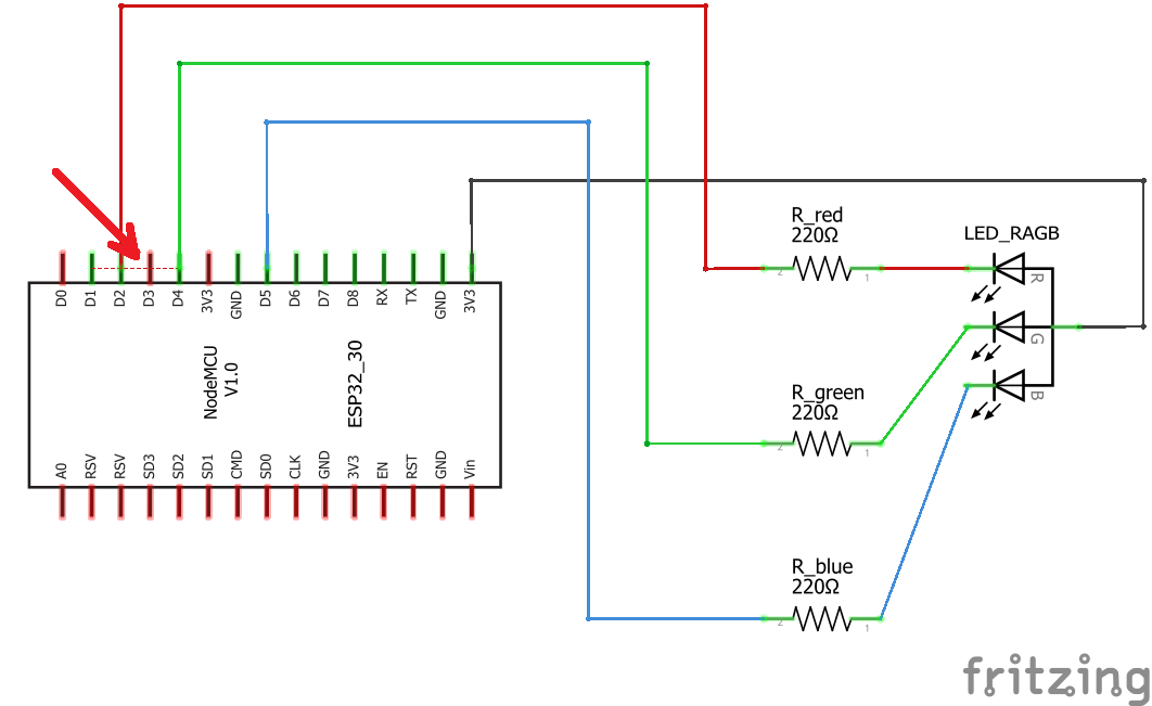
As you see it doesn’t look much like the original picture. Clicking on and routing the wires produces this which should be a representation of schematic (although it doesn’t look much like it!)
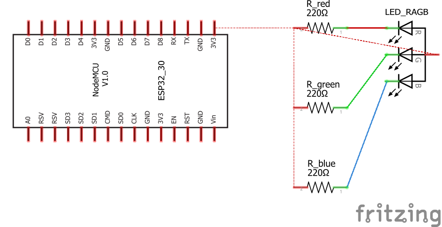
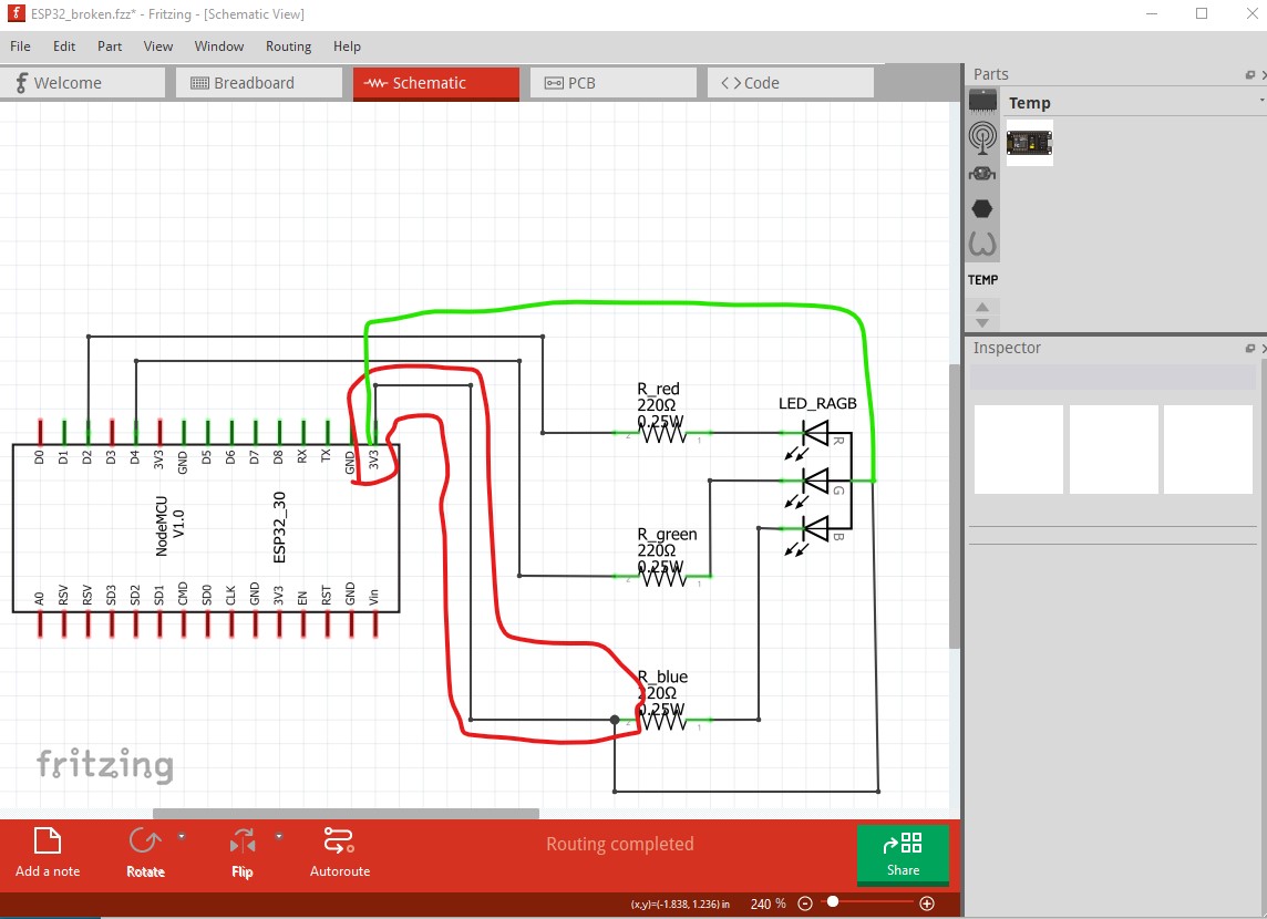
The wire to the resistor (circled in red) is presumably wrong. It should connect to a digital I/O pin not 3.3V. As it stands the blue LED will never light because it is connected to 3.3V instead of a digital I/O pin. You are best to make all connections in one view then click on the rats nest lines in the other 2 views to make the associated connections (and correct them if they are wrong in the original view!)
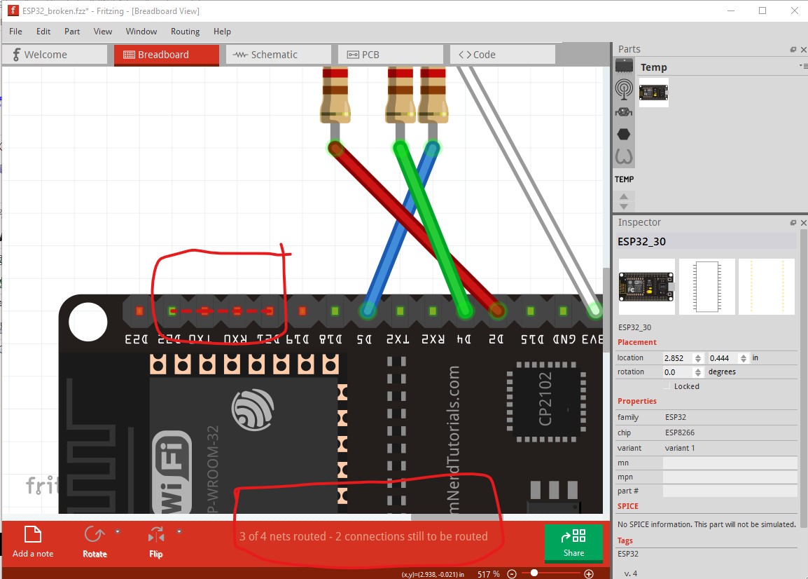
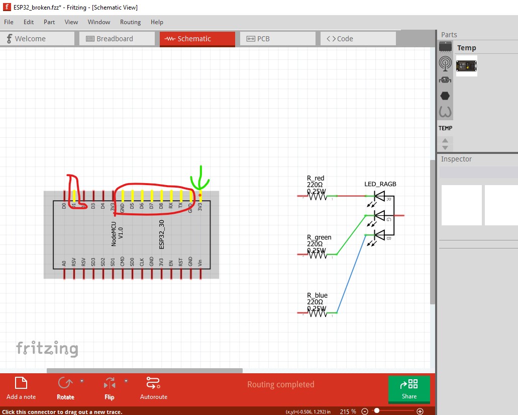
With all that said, it looks like the real problem is that the node mcu part is broken. Here I disconnected all the wires from the node MCU and then left clicked on the 3.3V pin. All pins that are bussed together light up yellow (which is way to many pins indicating the part is broken!)
only the 3.3V pin with the green arrow should be lit yellow. You need to find a better Node mcu part than the one you used. There are lots of them around (a google search of the form (“fritzing part esp32 node mcu” should find a bunch) then you need to check and make sure the part actually works correctly and matches the cpu board you have (clicking on the pins and making sure only identical pins such as GND or 3.3V light yellow is a good start) and go from there.
edit:
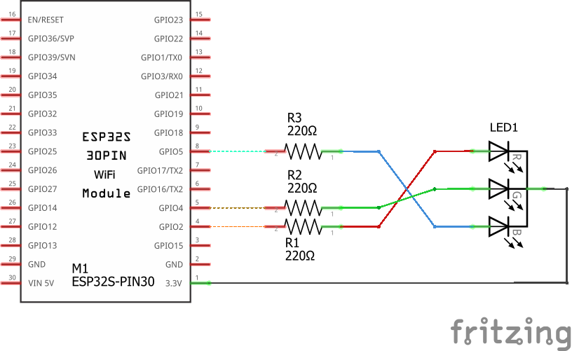
I started to check the part, and when I did that I discovered I had already seen it. The corrected version is here
you can replace the current one by doing a delete minus of the part. That will delete the part but leave the wires. You then need to load the fixed one, move it in the sketch and then drag the wires to the new part to connect them.
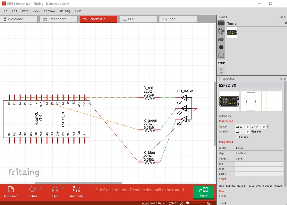
Looks to be operator error. You have miswired schematic compared to breadboard.
Sorry, but after posting I tried further on and edited the sketch to connect to D2, D4 and D5, because I don’t see RX2, TX2 and D18 in the circuit view.
I add. made the red, green and blue wires “fixed”. The dotted connections you marked was set by Fritzing and I don’t see any reference to those pins wired, thus I don’t know why it marks them connected.
So this (see below) was the best I could achieve. Still there is a suggested connection in the circuit view that I don’t understand (red arrow).
But in the end you approved a broken part and I will have to look for a replacement. Thank you very much for your effort.
Yep, GPIO16 should be RX2 not TX2. I will replace the improved .fzpz with a corrected on. I didn’t change the moduleId so you will have to delete the current part then close and restart Fritzing to be able to load the new one.
edit
Done. The part in the original post has been updated.