I’m following-up a previous Topic with a Concise posting (with Example and Code… in Fritzing)
Example:
Using IR receiver 1838 an Panasonic Cd Player’s Remote (but, most any IR-based remote will work along with most any IR receiver (just be sure to Hook it up correctly per Specification).
Code:
This simple code uses one of the Atmel chip timers to Generate a Square-Wave @ 38.4kHz.
That enables paring with output from remote. The timer’s implementation is well-known and often used.
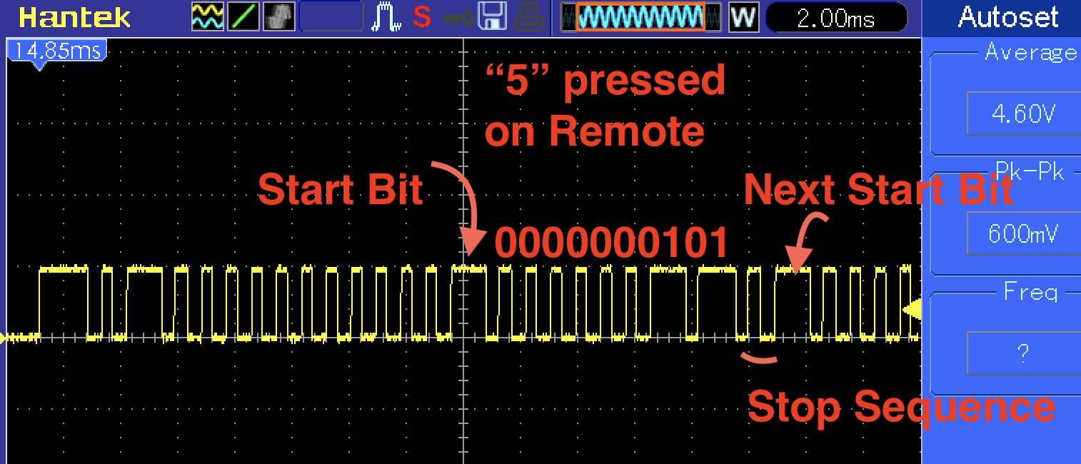
The image shows a capture on O’Scoope with decoding info of the Number ‘5’ button pressed.
This stuff can be confusing to Newbies but, a small amount of homework = knowledge!
Code is included… It should be on the Code tab in the attached .fzz file but, it’s also added at end of this post…
forU.fzz (6.4 KB)
The Code:
/* Reads IR recvier on Analog Pin
Uses “38.4kHz_Timer and IR_Analog_Tester codes; Combined into this single code”
Reads Sony/similar Remote Control
Wave form will be seen on pin D3
Pulse received from Remote Control will be seen on A0
Feb 5, 2019 Rev -0-
*/
int IR_recvrPin = A0; // IR signal input (can also see this Pin on O’scope)
int IR_recvrInput = 0; // variable to store the Input coming from the IR_recvr
volatile byte pulse = 0;
void setup() {
Serial.begin(9600);
setIrModOutput();
TIMSK2 = _BV(OCIE2B); // Output Compare Match B Interrupt Enable
}//end setup
void loop() {
IR_recvrInput = analogRead(IR_recvrPin) * 5 / 1023;
Serial.print(IR_recvrInput, BIN); // useless info
Serial.print("\t");
Serial.println(IR_recvrPin, BIN); // useless info
}//end loop
//================================ SUB’s and ISR, Timer… =========================
ISR(TIMER2_COMPB_vect) { // Interrupt Service Routine to pulse the modulated pin 3
pulse++;
if (pulse >= 8) { // change number for number of modulation cycles in a pulse
pulse = 0;
TCCR2A ^= _BV(COM2B1); // toggle pin 3 enable, turning the pin on and off
}
}
void setIrModOutput() { // sets pin 3 going at the IR modulation rate
pinMode(3, OUTPUT); // outputs the Frequency wave
TCCR2A = _BV(COM2B1) | _BV(WGM21) | _BV(WGM20); // Just enable output on Pin 3 and disable it on Pin 11
TCCR2B = _BV(WGM22) | _BV(CS22);
OCR2A = 51; // defines the frequency 51 = 38.4 KHz, 54 = 36.2 KHz, 58 = 34 KHz, 62 = 32 KHz
OCR2B = 26; // deines the duty cycle - Half the OCR2A value for 50%
TCCR2B = TCCR2B & 0b00111000 | 0x2; // select a prescale value of 8:1 of the system clock
}