Invert images of exported files

i’m trying to make a screen that can mask off my pads and screen print ink around them. leaving pads copper exposes for soldering.
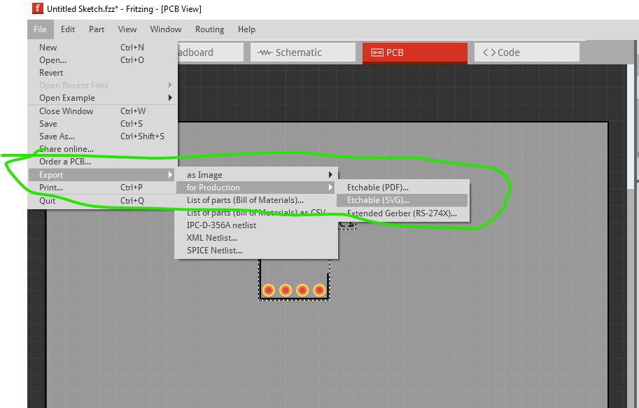
to burn a screen i need the photonegative of the solder mask. is there an option to do this in fritzing

or is there a process in inkscape to do this. i tried to just change the color of the svg exported from fritzing. but it is not a normal svg and editable?
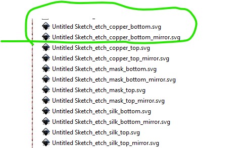
This

should do what you want. It exports the file and their mirrors as svgs (in this case) or pdfs as you choose.

capture1

Peter

no,
this just mirrors the image. i’m looking for…
if the traces and pads are black , i want to have the traces and pads be white, and the area around them be black. kind like a photo negative

Ah! I though that is what the mirrored svgs did, but it is not. Then you need to edit the svg with a text editor and do this (here I used vi, but your editor of choice should work as long as it has global replace.)

from

 <g partID="57920">
  <g id="board" >
   <rect fill="none" fill-opacity="0.5" height="159.424" id="boardoutline" stroke="black" stroke-width="0.5" width="239.424" x="0.288"  y="0.288"/>
  </g>
 </g>

to

 <g partID="57920">
  <g id="board" >
   <rect fill="black"  height="159.424" id="boardoutline" stroke="white" stroke-width="0.5" width="239.424" x="0.288"  y="0.288"/>
  </g>
 </g>

then the pads

from

 </g>
 <g partID="57960">
  <g transform="translate(105.28,31.68)">
   <g id="copper0" >
    <rect fill="none" height="3.96" id="square" stroke="black" stroke-width="1.44" width="3.96" x="2.34"  y="2.34"/>
    <circle cx="4.32" cy="4.32" fill="none" id="connector0pin" r="1.98" stroke="black" stroke-width="1.44" />
    <circle cx="25.92" cy="4.32" fill="none" id="connector7pin" r="1.98" stroke="black" stroke-width="1.44" />
    <circle cx="4.32" cy="11.52" fill="none" id="connector1pin" r="1.98" stroke="black" stroke-width="1.44" />
    <circle cx="25.92" cy="11.52" fill="none" id="connector6pin" r="1.98" stroke="black" stroke-width="1.44" />
    <circle cx="4.32" cy="18.72" fill="none" id="connector2pin" r="1.98" stroke="black" stroke-width="1.44" />
    <circle cx="25.92" cy="18.72" fill="none" id="connector5pin" r="1.98" stroke="black" stroke-width="1.44" />
    <circle cx="4.32" cy="25.92" fill="none" id="connector3pin" r="1.98" stroke="black" stroke-width="1.44" />
    <circle cx="25.92" cy="25.92" fill="none" id="connector4pin" r="1.98" stroke="black" stroke-width="1.44" />
   </g>
  </g>
 </g>
</svg>

to

(via these vi commands.

edit:

screwed up the vi command it should be with the fill left at none (the background changed in the edit above!)

:.,$s/stroke=black/stroke=“white”/

which does the same for stroke and thus inverts the image as I believe you want. Which then looks like this

Peter

cool i’ll give it a whirl. thanks again