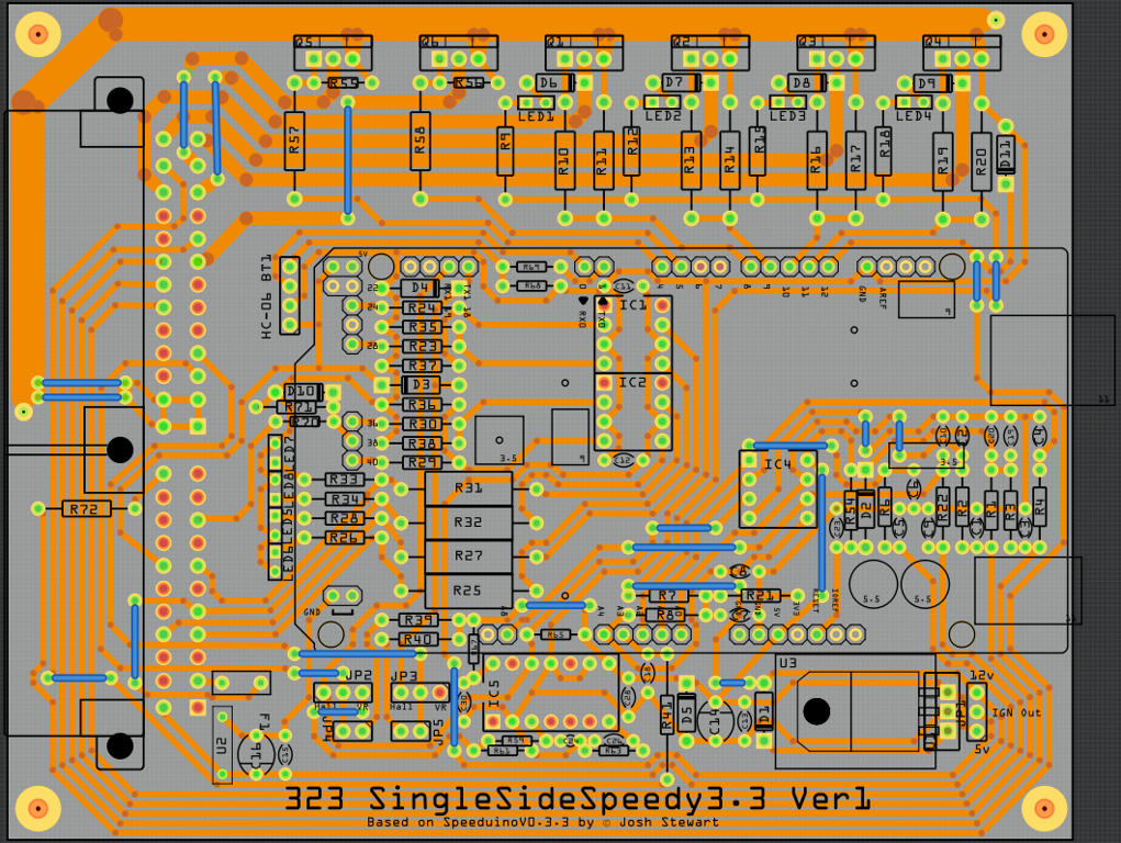
i just created a simple circuit which includes 5 pcs 74HC595 shift register and 5 pcs 7 segment displays. Since i live in Austria i need to buy the 7 segment displays on the local market. The order of the connections is different to the ones from the fritzing library. Here is my problem:
Even though i connected the 7 segment displays correctly on the bread board page the autorouting is ignoring it and creates wrong connections on the cicuit. E.A. my 7 segment display have the common cathode on 3 and 8. But the circuit autoroutes them to 9. The segments as well are wrong routed.
I even tried to change the connections in the parts editor but it gets completely ignored.
Looks like the part doesn’t have constant #ing and might be confusing, so I think you have to fix the part.
Right-click the 7-seg and Edit
Go to BB view and click C in the table
Now go to PCB view.
See how a different pin is highlighted.
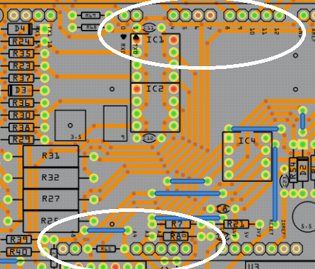
The trick with auto routes is that you never use auto route, you manually route. Pros don’t really use AR either.
Can you see the difference with my manual routing.
Sorry I thought they were all the same. Those headers are drawn in the Arduino part, and unfortunately don’t come in that shape. And I think if you make the part, it won’t be a CORE part, so won’t be adjustable in Inspector. Basically it will be a new part for every header number. Maybe Van might know I way, but I don’t.
You would need to make either a custom part or a code change (the connectors are made by the parts factory in the code) then rebuild from source. This doesn’t look like a case where you can pretend to be a core part to get what you want.
You can type a value (up to somewhere around 120 as I recall) in to the trace width window and it will give a larger trace.
I should create some custom parts, 1p, 2p, 3p would enough… or maybe also 6 & 10p…
That would be easy…
I don’t think, I can do changing the core code…!!!
But, If there is any tutorial/example for code changing, you give the link… I’ll give it a try…
Don’t I wish . There is the source (practically no comments) and that’s it. There are sketchy directions to build a development environment that have taken me close to 2 years to get up. At present there are some parts in the parts repo (which I am working on replacing) which cause Qt (the framework Fritzing runs on) to assert and die. Maybe sometime soon there will be progress but don’t hold your breath . If the dev stuff was up and running this would be fairly easy (I have some fixes for code factory already.) Its fairly easy to get an build on Linux going, but Windows is being a problem.