That looks better ![]() . Still two minor problems: the icon is still 8 pin, to fix that either copy the breadboard.svg file to the icon.svg file (using the correct file names) or in parts editor in icon view file->reuse breadboard image. As well in schematic the connector terminals aren’t defined in the svg so the connector is defaulting to the middle of the pin:
. Still two minor problems: the icon is still 8 pin, to fix that either copy the breadboard.svg file to the icon.svg file (using the correct file names) or in parts editor in icon view file->reuse breadboard image. As well in schematic the connector terminals aren’t defined in the svg so the connector is defaulting to the middle of the pin:
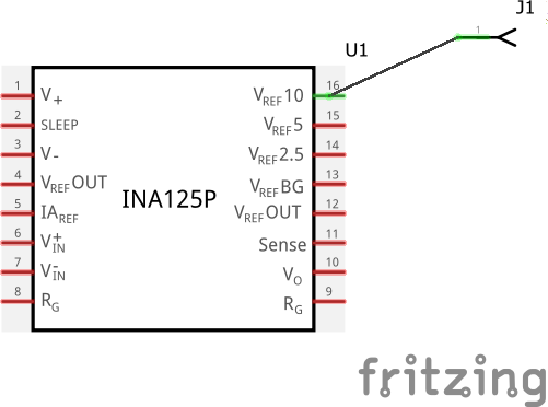
where it should be on the end of the pin as is the case with the connector. To fix this in parts editor (although I have never managed to make it work ![]() ) you select the pin and set the direction (west in this example I think). In the svg and fzp file you define a rectangle (I usually use .01 as the size), place it on the end of the pin (connector15pin in this case) and call it connector15terminal. You then need to add a definition in the fzp file to specify a terminalid. Doing it via parts editor (which I suspect you are) is detailed in Old_Grey’s video tutorials:
) you select the pin and set the direction (west in this example I think). In the svg and fzp file you define a rectangle (I usually use .01 as the size), place it on the end of the pin (connector15pin in this case) and call it connector15terminal. You then need to add a definition in the fzp file to specify a terminalid. Doing it via parts editor (which I suspect you are) is detailed in Old_Grey’s video tutorials:
Peter