hello everyone, i am still new in fritzing, i have a problem with my schematic diagram, it stated that there are 12 of 15 routed - 6 connection still to be routed. I don’t understand this as my breadboard diagram shows that all has been completely routed.
Can someone help me with this?hc-05-serial-2.fzz (33.7 KB)
You are going to have to fix that SCH first because there are parts miles away from the circuit. Bring those parts close to the Arduino, because they are so far away that I can’t see all of it at once due to it being microscopic.
EDIT
There is a lot more wrong than I thought.
I suggest going to SCH view, Routing/Select All Traces, then Edit/Delete.
Do the same in PCB view. You need to disconnect all solid connections in other views so they become ratsnest or you will destroy the sketch when you change connections in the primary view.
Now go to BB view and fix all the problems.
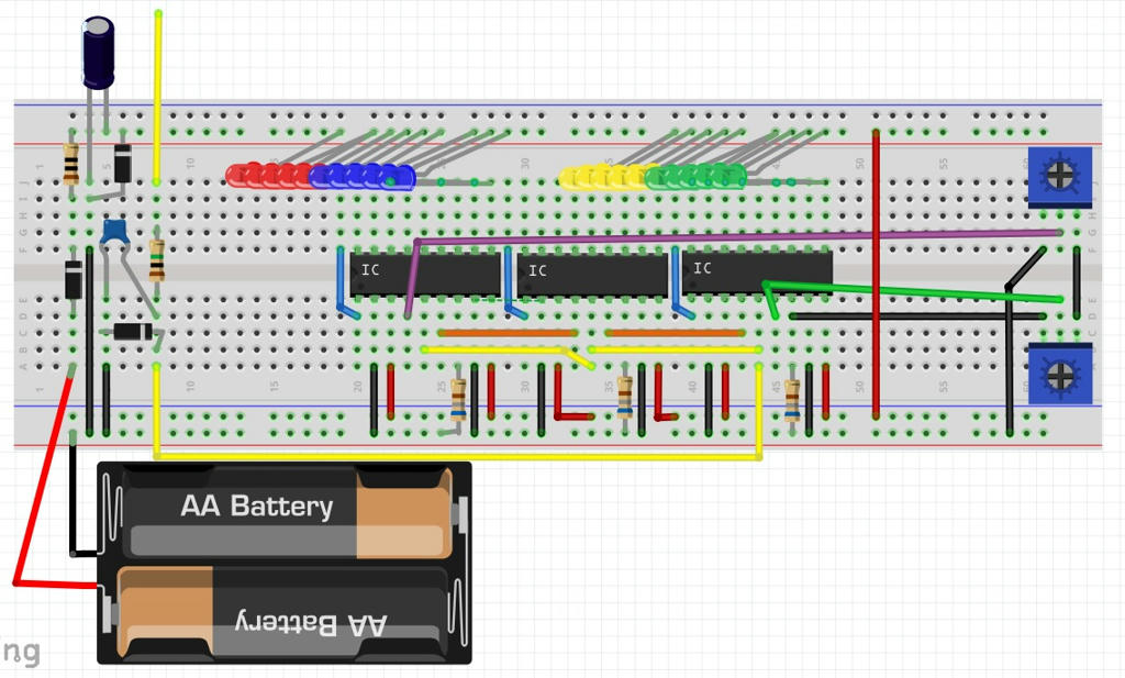
See the red TXD pin on HC-05, that is showing you it’s not connected.
Red pins on the UNO too.
N trans is not in BB, ie red dots
Pin 7 of L293D is not connected to yellow wire. Click on pin 7 and you will see no junctions on the yellow wire turn yellow, just the row on the BB
Red bendpoints on yellow wire not connected.
Check the whole thing for red pins, and click on green pins to follow connections to make sure it’s definitely connected. Remember if things are touching it doesn’t mean anything is actually connected, it’s like all EDAs there is no snap connect for touching stuff.
thank you sir for helping me out, I am trying to do as what you’re suggested.
with deleting the solid connections, makes me ease the work at least (less mess) , and I want to ask, If I need to do correction of the SCH so I have to do the same correction on PCB?
You need the BB view perfect first, and if you try to fix it without deleting all the solid traces in the other views it will corrupt the sketch and you will have to throw it away because it will be impossible to fix.
After you fix BB view - you can post it again for checking - do the next view and trust the ratsnests. You can click on a pin and everything connected will turn yellow, and that might give you an idea of a shorter route. If you need a junction put a bendpoint on the trace and run a trace to it - hold ALT and click and drag a trace to the pin -. Always grab junctions and move them to make sure traces stay connected.
1 Like
I have done for the BB view, but I don’t quite sure it is right or not. It looks correct ahaha, but could you please check my battery connection and the I am not sure in connecting 5V and Vin in arduino, because I am using the 9V and 3V of dc battery.hc-05-serial-2.fzz (26.1 KB)
I’m not very good at knowing if that actual circuit will work, so unless you tested it working someone else will have to look at it.
In BB I like to make sure it looks very clear so people can’t make mistakes. It’s not critical because I think it’s ok, but little things like :-
The diode near the button looks like it’s not touching the hole when it’s connected to the hole under.
I would move the N trans up 1 so you can see the leg and blue wire are actually. I like pin and wire on separate holes and not on top of each other.
I also tend to not run wire over BB holes but between so there is no chance of something connected by accident. Things like the white wire near the resistors.
Possible errors are
red wire near #15 on BB not going anywhere
I don’t think you can put 2 wires in the same header hole on the UNO
Some hints
This doesn’t look correct, but I’m not sure what should be happening. Is the 9V battery powering the Arduino (alternatives would be a wall wart connected to the arduino power plug or a USB cable plugged in). If so the +9V side needs to go to Vin and that 9V will be reduced to provide 5V and 3.3V on those pins. Both the 9V battery and the 3V (12V as the note says?) batteries appear to be connected wrong. I’d expect the - side of both batteries to go to ground (which by the way should have black wires usually). The +9V wire should go to arduino vin and the 3v/12v battery + should likely go to the motors. The diodes across the motor will likely mean that the motor will only go one direction (the other direction will likely short the motor driver). Usually motor drivers have internal protection diodes but you would need to check the data sheet to see if that is true here. What connects to the power plug on the bottom?
Peter
I was planning to run my device with external 12V dc battery and also I want to make it rechargeable too , so I guess I need to add ac adapter socket and its charger but i can’t find reference on it. I also have difficulties in connecting the 9v battery and 3V battery in series (I found one source of someone tried to connected like this but when I tried, it is not connected to the 3V)
Ah, that explains a few things! Indeed you have a number of problems and as it stands you are likely to blow up the Arduino. Your problem with the batteries is a Fritzing quirk, the bendable leads on the battery are both female and thus won’t connect to each other. You need to run the wires from the positive of the 9V battery to an empty row on the breadboard and then connect the negative wire from the 3v battery to the same row on the breadboard to actually get a connection (this is why schematic shows the batteries to be unconnected to each other).
Edit: I just realized you could also connect a wire (which will connect to either a male or female connection) between the +9V and the -3V supplies without needing to use a breadboard strip. Either should work.
Your current connection would work in real life but not of Fritzing. Alternately you could use only the 9V battery and note that it is in real life a 12V battery. Now the negative side of the battery wants to go to ground and the positive side of the battery wants to go to Vin on the arduino (I recall checking the schematic for the arduino once and deciding that you could power Vin from there if you didn’t use the USB connector or the barrel jack on the Arduino but you may want to verify that). The Vin connection (expecting 9 to 12V in) feeds voltage regulators on the Arduino that provide 5V and 3.3V out to the pins labeled that. You are attempting to put 12V on the 5V output to the Arduino which is likely t blow the board. If your motors want to run from 12V (which is likely, the Arduino regulator can only supply a limited amount of current at 5V and likely won’t run the motors successfully) they too would need to connect to the battery positive or the Vin pin. Motor U4 is connected wrong. It should connect to the motor output on the LM293 not the IO pin on the arduino (which doen’t have the capacity to drive a motor and would probably damage the Arduino). I’m unclear what the transistors and diodes are supposed to do, but I don’t think it is correct. As noted before the motor driver probably has appropriate back emf protection but you would need to verify that (a quick look at the data sheet indicates that is correct). In your current configuration the motors will only go one direction (which may be what you want), to go both directions you would need to use two drivers per motor (i.e. one l293d will only drive 2 motors bidirectionally). I don’t think you need either the transistors or the diodes. Hope this helps some.
Peter
1 Like
Thank you so much Peter. It helps a lot! Can I connect two wires on the same digital pins i.e D04?
To my surprise that appears to work (I’d never tried it and had to make a test sketch to see if it would work). I dragged in three 2 pin headers in to breadboard and connected one pin from the first two to a single pin on the third in breadboard, then switched to schematic. In schematic the connections are correct. It is however probably a bad practice because on a real Arduino you can only get a single wire in to the header and the idea in breadboard is to have something you (and someone else using your sketch) can physically wire up, so you should use a breadboard strip so each wire has its own hole. It is also likely to make verifying the connections are really connected more difficult as sometimes a connection can look like it is connecting on the screen but it a bit off and there is really no connection in the other views. A good connection should go green (rather than red) and when clicked on everything connected should go yellow but with two wires on a single pin I’m not sure what will happen if one wire is connected and the other isn’t (I suspect the other end of the non connected wire won’t light up yellow, but that may not get noticed).
Peter
1 Like