As you may have noticed we are trying to avoid doing your homework for you while assisting you in figuring out what you need to do  . To that end here are a couple more suggestions. Here I have put two resistors on the breadboard
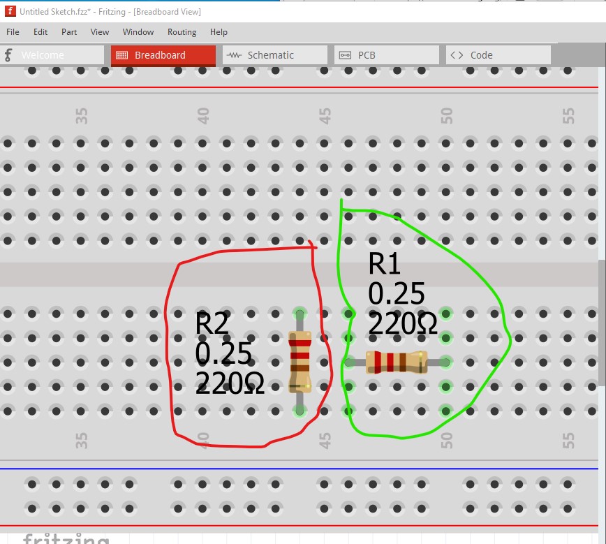
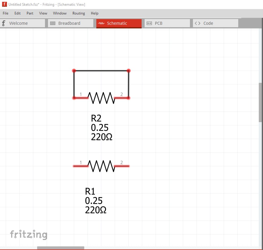
Here R2 (circled in red) is incorrect. R1 (circled in green) is correct. When I switch to schematic view the error becomes obvious, because the entire 5 pins that R2 connects to are connected together R2’s pins are shorted (indicated by the rats nest lines connecting the two pins.)

R1 is correct in that there is no connection between the pins. If I click on the rats nest line and drag it you can see the short (reflected in to schematic view from the connection in breadboard.)
Something else that may help, in any view (breadboard in this case) if you hover on top of a pin with the mouse and left click, everything connected to that pin will light up yellow like this
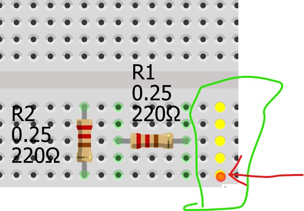
here the red circle which the red arrow points to is where my mouse is centered and left clicked. That shows that all 5 connectors in that row are connected together. That is why R2 is shorted because both ends are connected to pins that connect to each other. The power rails on top and bottom are all connected together horizontally to allow distributing power across the boards (left click on one pin to see!)
Peter