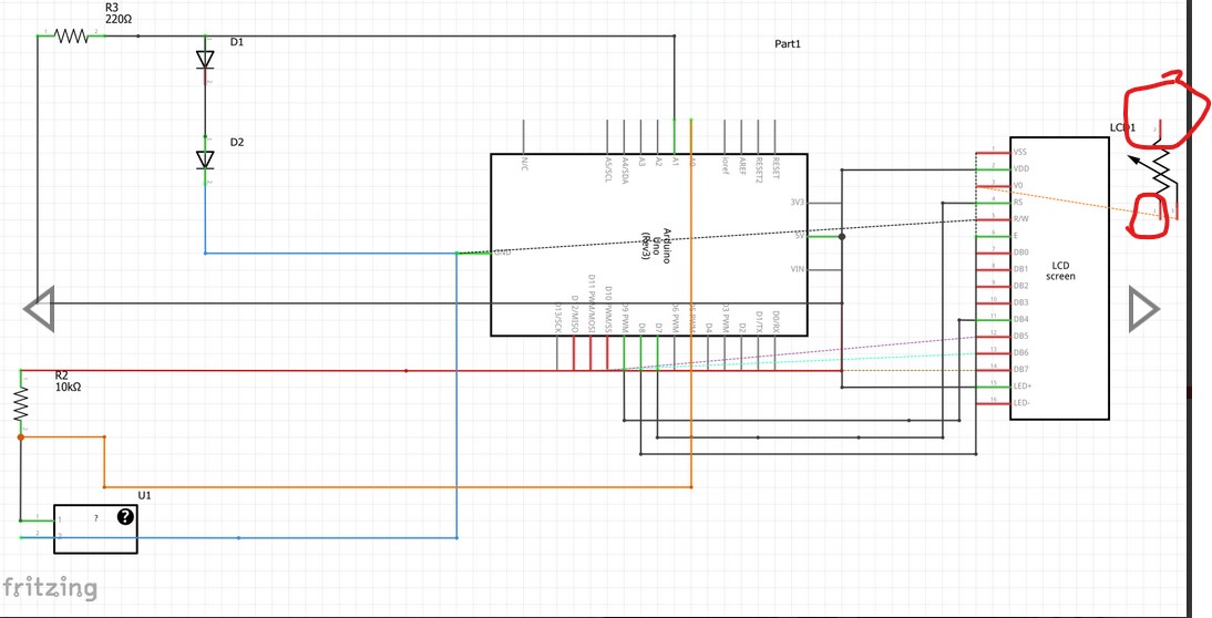
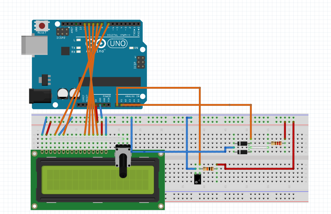
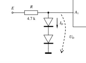
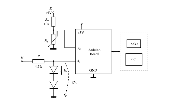
I’ve received a Uni assignment where I need to build a breadboard implementation of the following schematic:
The part with the LCD is already implemented (based on some instructions we received on how to connect each pin of the LCD display to the Arduino board).
The problem is, I seem not to understand how to connect the Resistor and the Thermistor in parallel, and the result to pin A0 Arduino. Also, same for the two diodes.
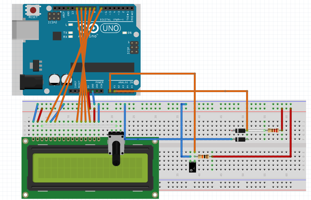
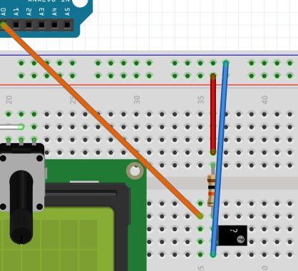
This is what I tried:
Unfortunately, it seems that the Resistor and the Thermistor aren’t properly connected in parallel.
I’m new to breadboards, didn’t use them before, so I am sorry if I ask questions that require a trivial knowledge - I don’t have this either.
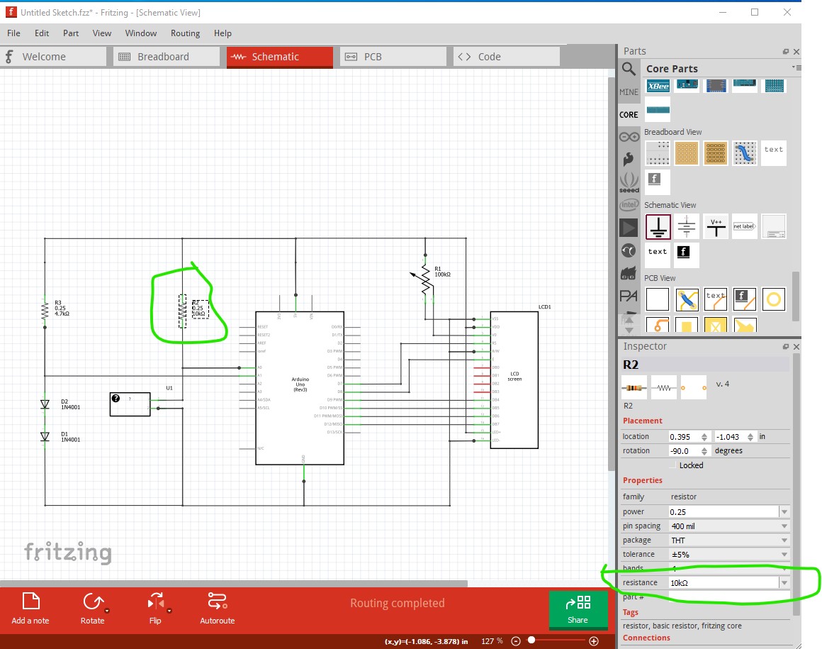
I was talking about schematic view. It showed the resistors in series. Nothing to do with the where the components are placed on the breadboard and in the breadboard view.
This breadboard layout is still not correct. You need to figure out which holes in the breadboard are connected together, then place the components where the leads are on different wires. As is, the both leads of the variable resistor are connect to the same wire inside the breadboard. The orange is is also no longer connected to either the fixed or variable resistor.
Could you, please, provide me an example at least on how to connect the resistor and thermistor in series, together with the Arduino A0? As presented on the circuit? I still don’t get the idea.
Each group of 5 circled breadboard holes are connected together (wired) inside the breadboard. Where you have placed the thermisitor BOTH ends are connected to the same wire. That shorts them together. You need to rotate the thermistor 90 degrees (turn it sideways) so the each lead connects to a different group. Then you can add wires as needed to connect to power, ground, and other components. Using the other holes in the groups the component leads are inserted in.
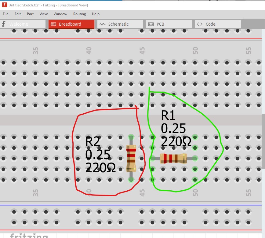
As you may have noticed we are trying to avoid doing your homework for you while assisting you in figuring out what you need to do . To that end here are a couple more suggestions. Here I have put two resistors on the breadboard
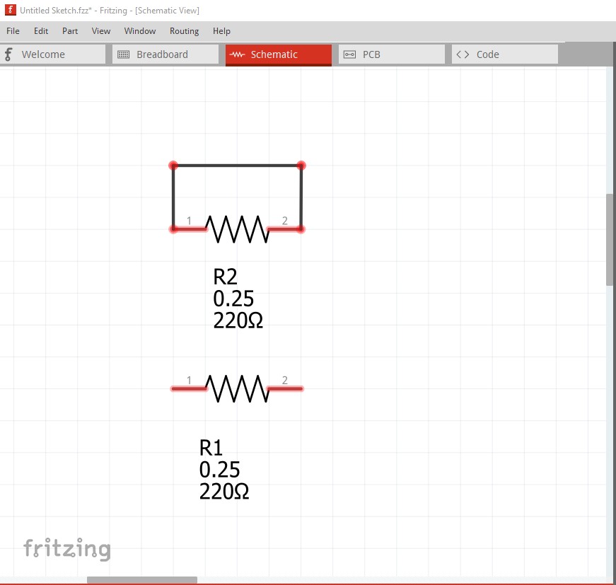
Here R2 (circled in red) is incorrect. R1 (circled in green) is correct. When I switch to schematic view the error becomes obvious, because the entire 5 pins that R2 connects to are connected together R2’s pins are shorted (indicated by the rats nest lines connecting the two pins.)
R1 is correct in that there is no connection between the pins. If I click on the rats nest line and drag it you can see the short (reflected in to schematic view from the connection in breadboard.)
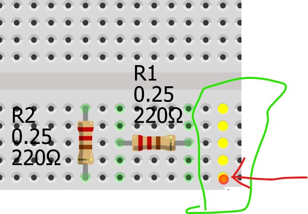
Something else that may help, in any view (breadboard in this case) if you hover on top of a pin with the mouse and left click, everything connected to that pin will light up yellow like this
here the red circle which the red arrow points to is where my mouse is centered and left clicked. That shows that all 5 connectors in that row are connected together. That is why R2 is shorted because both ends are connected to pins that connect to each other. The power rails on top and bottom are all connected together horizontally to allow distributing power across the boards (left click on one pin to see!)
I’m obviously not trying to make you do my homework. I was just confused regarding on how I should connect all this stuff. Never used a breadboard before and I am still confused about it.
Also, thank you a lot for your answer!!!
To my eyes, neither of those match the previous schematic image.
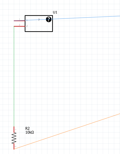
You could start by wiring the parts together in schematic view (deleting the wires in breadboard view first, and moving the parts off of the breadboard). If you can get the wires between the parts correct on schematic view, Fritzing has tools to help match the circuit wire across views. If one view is wired, then the other views will show “ratsnest” wires (dashed lines on the screen) where pieces need to end up connected together. Like those shown on the schematic view above. Which does NOT match the earlier schematic of the resistors. That earlier snapshot shows one end of the fixed resistor going to 5 volts, the other end of that resistor connecting to both pin A0 and one end of the thermistor (variable resistor), and the other end of the thermistor going to ground. Assuming the red rail (row of holes next to the red line at the top of the breadboard image) is 5 volts, one end of the fixed resistor is (correctly) going to 5 volts, but the other end of the fixed resistor is ONLY connecting to the thermistor. Pin A0 is connecting to the other end of the thermistor, and there is no connection to ground.
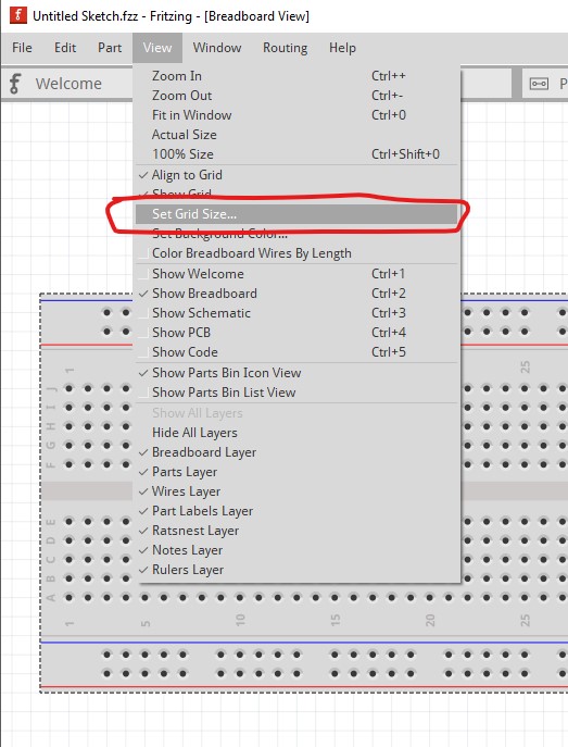
Make sure that Align to Grid (two above the Set Grid Size) is ticked, if it is not click on it to activate it. That will cause parts to snap to the grid (it is probably on, but some of your wires are misaligned and that can be the cause!)
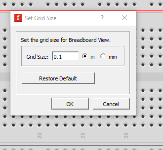
which brings up this
if yours doesn’t look like this, click the Restore Default button which will change it back to this. Now on to your images.
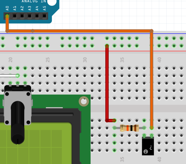
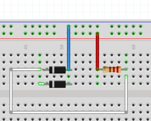
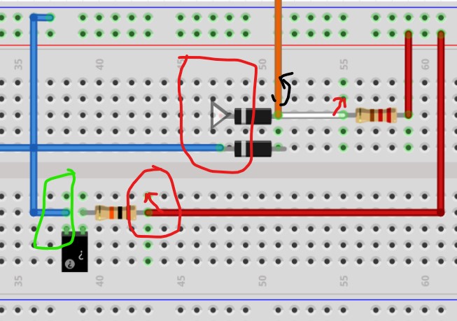
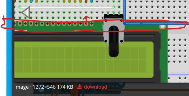
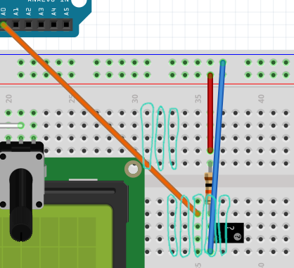
The mystery part (probably the themistor) circled in green is correctly connected. Each hole in the breadboard has a single pin in it and the row is a (faint) green color indicating a successful connection. The resistor beside it is connected but incorrect in that the red wire is on the same pin as the resistor. This works in Fritzing but not in real life so move the red wire up one row to an empty pin (shown by the red arrow.) The two diodes above the resistor are incorrect. The bottom diode has a connection to the wire (which as above should be in its own breadboard pin not the same one as the diode) but not to the breadboard, as the breadboard row is not green. That means it is not connected to the diode just above it as it should be. Also move the orange wire up one slot so it doesn’t share the pin with the diode. You may need to click on each diode in turn and move it slightly to the left or right to get it to connect to the breadboard (this is a Fritzing oddity, it needs movement to make the connection.) The breadboard row should turn green to indicate a successful connection. Both the orange and white wires on the diode pin should be moved to their own hole in the breadboard. Clicking on a pin in the breadboard will light up everything connected in yellow, so once this is done do that and check that everywhere the wires and parts are supposed to connect lights up yellow. If they don’t move those that don’t light up until they do.
Similarly the LCD board is not connected in this image (it appears to be connectiing in schematic though so this may have been corrected!) As shown by the red arrow it needs to move up one row to actually connect to the breadboard because the top edge of the LCD screen is below the last row of the breadboard connections and thus the LCD won’t be connected to the breadboard.
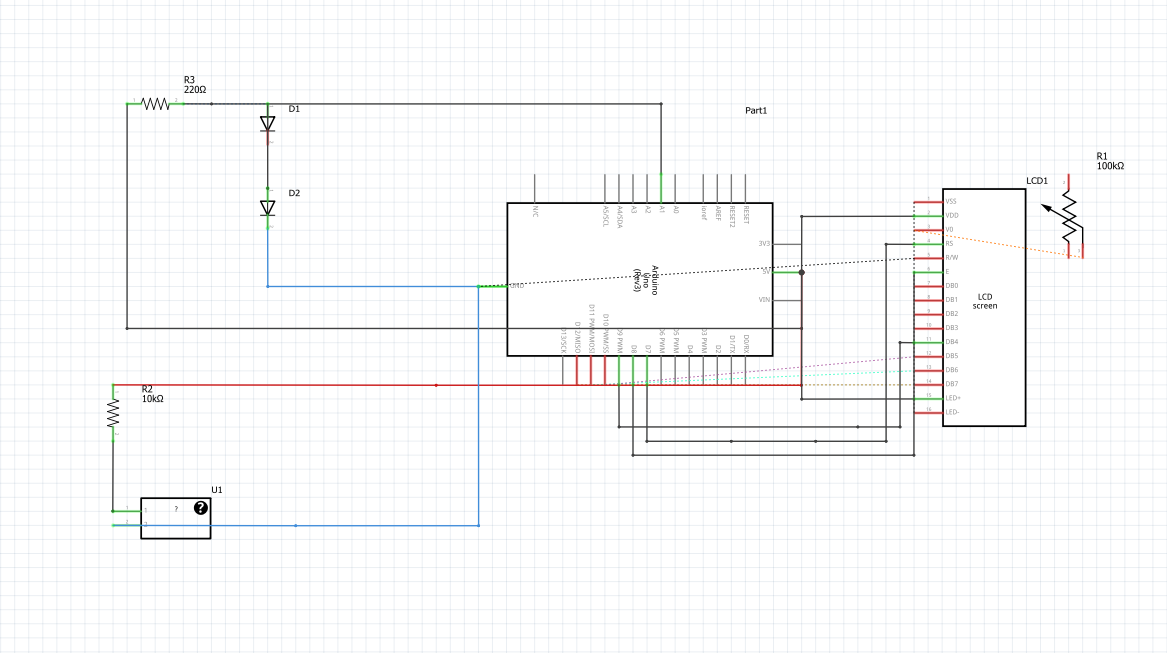
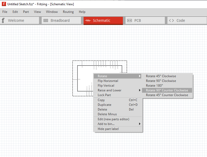
The schematic indicates a problem, the pot on the LCD display is not correctly connected. The wiper (the middle pin) is connected, but the two end points (one to 5V and one to ground) are not as neither have connections in schematic. In breadboard there is only a white wire from the wiper to the LCD pin, the other two pot connectors need wires as well. As well you can make the schematic easier to read by right clicking on the Arduino and selecting rotate like this
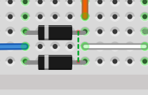
True, but I don’t think they are connected to the breadboard. The wire is likely the connection on the bottom one, and the top cathode doesn’t appear to connect to anything. On its anode I think the wire is what is causing the breadboard connection, it isn’t clear the diode is connected to anything!
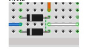
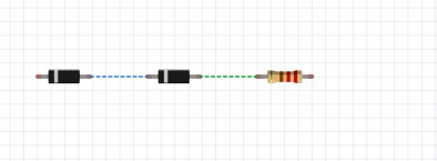
This is getting closer, however there are still at least two problems: the diodes (as @microMerlin commented above) are in parallel when the schematic says (and was wired as, in the schematic in Fritzing) they should be in series. If you move both diodes off the breadboard, the rats nest lines from schematic should show how they should connect in breadboard.
This
is not the same as this
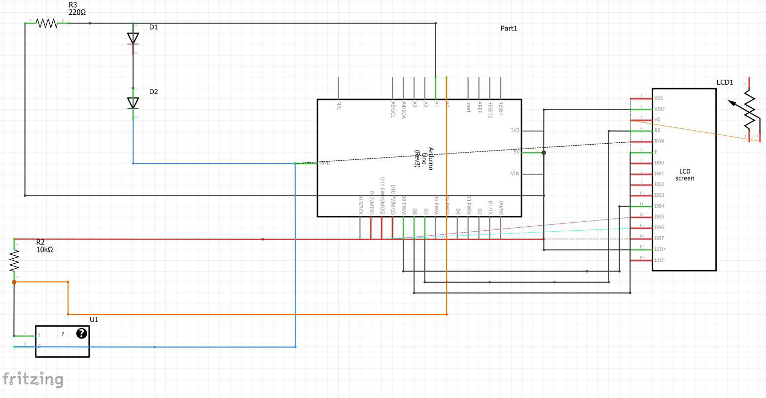
moving the diodes off the breadboard should make it look like this (assuming schematic is the same as it was earlier)
From where the rats nest line is in breadboard (it does not match the connection that was in schematic above) you may have triggered a Fritzing bug where the routing database gets corrupted. So first try and correct the diodes and see if the rats nest line disappears when the diodes match the connections in schematic. If they don’t (or rats nest lines that aren’t in schematic appear) you have likely tripped the bug. The only solution I know of is to delete all the wires (“Routing->Select all wires” then hit the delete key in breadboard and “Routing->select all traces” and press the delete key in schematic) then rewire one or the other of breadboard or schematic entirely. Once that is done, follow the rats nest lines to route the connections in the other view. The second problem is that the pot on the LCD display is missing two connections (obviously in both breadboard and schematic since there are no rats nest lines in breadboard.) Fixing those two should make it work.
edit: One more thing: you need to set the values of the resistors to be entirely correct. To do so click on the resistor and in Inspector (the lower right window) click on resistance and set the value in the pull down menu to match the value in the schematic.
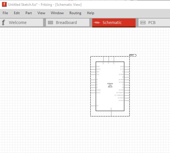
I would advise you to delete all the wires in schematic, then wire breadboard. Once breadboard is finished, switch to schematic move and rotate the components to match the schematic above (which is how a correct breadboard should look) and click on the rats nest lines to create the wires then drag the wires to the correct position. If when it is complete it matches the schematic above, then your breadboard is wired correctly.

 . To that end here are a couple more suggestions. Here I have put two resistors on the breadboard