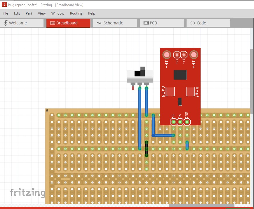
Both the leftmost pin of the switch and the pin of the relay connect to GND (in the schematic), which is also that horizontal stripboard trace. I wired it up like this:
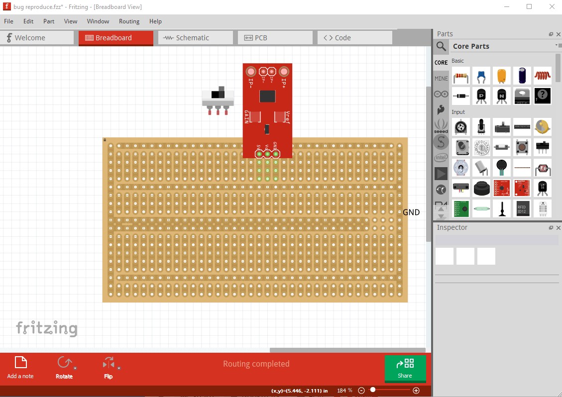
You have run across a Fritzing bug (which is still present in 0.9.10 which is the current version of Fritzing, 0.9.3b is over 6 years old at this point, so upgrading to 0.9.10 would be well worth the donation fee!) If you can reproduce this I would be very interested in the steps to do so (I have been unable to in more than 5 years of trying to!) The usual advise to avoid this is to make all you changes in one view (such as breadboard) then move to the other two views and click on the rats nest lines to make the connections. Making incorrect changes in the other views is believed to be what corrupts the routing database and produces the bogus rats nest lines, but as noted we have been unsuccessful at being able to recreate the issue, and without being able to recreate it we can’t fix it. To create this working .fzz file I started from you broken one
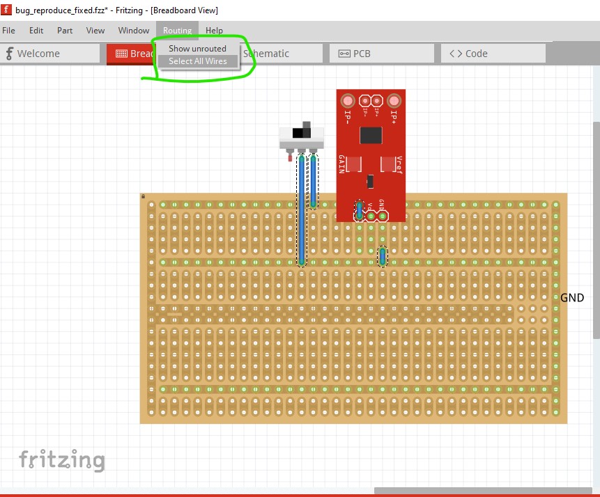
then starting in breadboard reconnect the wires. Then switch to schematic and click on then route correctly all the ratsnest lines which creates a correct .fzz file like this. This lets you keep the part positioning while making the .fzz file correct. There may be cases where even this won’t work in which case you need to start the sketch again from scratch (which is a massive pain with a large sketch!) Doing all changes in one view is known this from occurring though.
As noted I would be very interested in the exact set of steps that creates this, but usually it only gets noticed after the .fzz file is saved and reloaded. If you detect it before you save the .fzz file you should be able to use Edit->undo to undo the steps one at a time til the rats nest line disappears. At that point the redo command may make the rats nest line reappear (or if it is a timing issue it may not!) and the sequence of commands in the redo may help us figure out what is happening (especially if redo causes the rats nest line to reappear!)
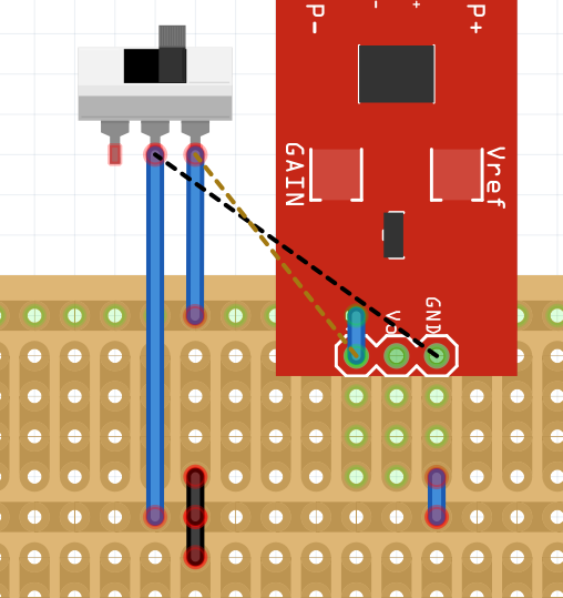
I would say that the problem is that the wires are not making conections. You can see your connectors are red (which means not connected). They should be in green, which means that there is a connection, like the ones of the red board.
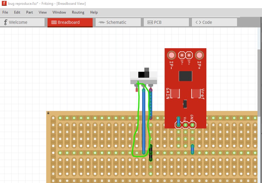
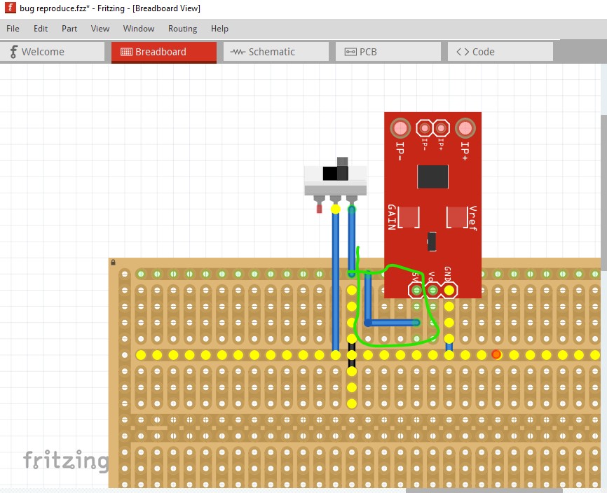
Here the connections circled in red are not connected (the connect point as @fai pointed out, are red not the correct green!) Note if you click (as I did here) on a connection it will light everything connected to it yellow. Note the ground pin on the board and the strip connecting it are not yellow and thus not connected. To fix this click on the end of each wire and move it slightly like this til the connection goes green
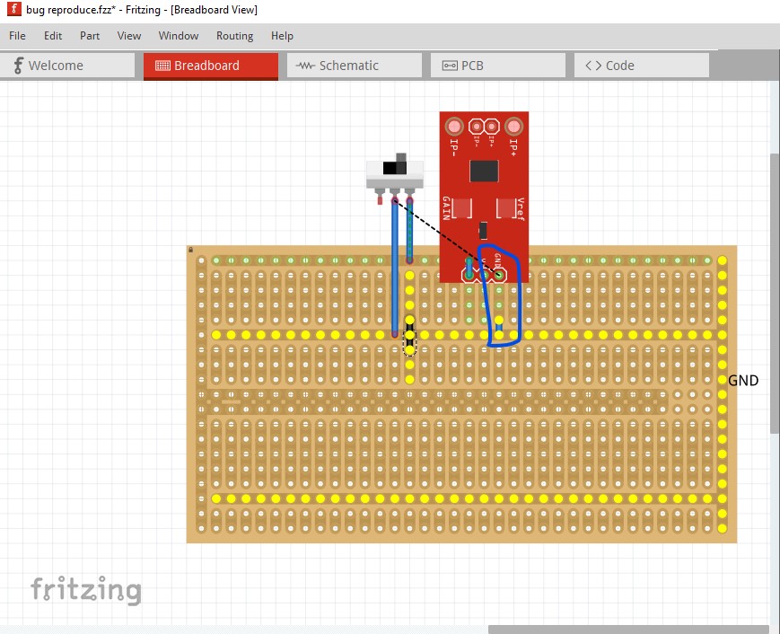
Then move the wire that connects through the board (which won’t work in real life!) to connect to a pad on the strip board instead like this (the new wire is circled in green here with the now correct ground connections highlighted in yellow indicating they are all correctly connected!)
Note that as connected the switch shorts ground on the board to +5V on the board which won’t work in real life, but I assume this was just a test example and the switch should be connected to a source of 5V and not to ground.