Hello, Friends!
Simple guestion :)…
If there is no the component in Library as i see, for instance -
logic IC - CD4001, what is the right and simple way to have one?
(If not to make the New component by myself…)
Regards,
Alex.
Hello, Friends!
Simple guestion :)…
If there is no the component in Library as i see, for instance -
logic IC - CD4001, what is the right and simple way to have one?
(If not to make the New component by myself…)
Regards,
Alex.
There are millions of parts, and the chances of finding one specific non-common part# is slim. FZ gets around it by using generic footprints where you just give it the specific part#.
If you can’t find it in Google just grab a part with the same footprint and change the part# in Inspector.
There is a generic IC part in the core parts, in the ICs category, the very first one in the list called IC. After dragging on to the board you can set the pin numbers, package, spacing, etc.
Thanks!
I see that Generic Element, but hen transfer it to the Principal Scheme
field - i see only rectangle with nubered pins.
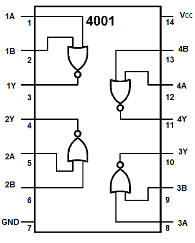
How can i transform this generic view of this component to the
view ordinary for instance for CD4001 - 4 logical elements with
2-OR-No function each?
I see it us simple must be ;), but it is strange - not see at moment How ;)?
Do you mean an image something like one of these…
Sorry, may be i do not understand the example you have posted …
My problem is simple - i see the IC generic Component, but its picture on Scheme is just only one figure with 14 pins, without 4 NOR logic elements.
How can i transform the generic figure to the needed?
Or may be some Advaneced Library exists where one can download
needed kibrary files?
Thank you. I shall try.
Do you mean something like this…
Yes, as the variant.
Google is your friend. A search for “fritzing part 4001” turns up
https://github.com/tomaskovacik/hw/blob/master/fritzing/parts/4001/TC4001B.fzpz
Which while not the drawing above is at least more than the standard generic part. To create a part with the drawing above you would need to create a new custom part by editing the schematic svg file with an svg editor such as Inksacape. In this case I’d probably start with this part as it has all the needed connectors and formating already done for you and all you would need to do is edit the square boxes in the svg to logic symbols. To get those logic symbols you can use copy/paste from other parts (I think most of the shapes are in the 4000 series parts posted and now in core). With more experience in parts making you could (or I could) make this in to a schematic subparts part where each individual gate can be moved by itself (this has performance implications however, a lot of them makes frixting slow). Last you could post your work here so others can use it as well.
Peter
Peter, THANK YOU,
enaugh info!
I shall try to study to do at the same way.
We study (with kids) several systems (Altium Designer, Altium Cirquit Maker and Studio, Eagle, Upverter, DipTrace…).
Now begin within Fritzing.
We try to find the best way for metodological optimized (for kids from
11-13 age and above) to begin Create and Disign - interest, simple, perspectively…
Different systems - some different ways and “rukes of life” ;), sure.
Thank you and other Fritzing-Friends.
Your are friendly and kind.
Regards.
Alexey Batin,
Ekaterinburgg, Russia.