Hello all,
Hope we are safe and well,
I am a complete newbie and have had a google for the following parts and wondered if they have already been fritzed or if I could request them to be?
Thanks for your time, any help greatly received.
Hello all,
Hope we are safe and well,
I am a complete newbie and have had a google for the following parts and wondered if they have already been fritzed or if I could request them to be?
Thanks for your time, any help greatly received.
Neither part appears to exist, both are easy enough to make, but the location of pin 1 for the QW/ST connector on the ICP10125 don’t appear to be documented anywhere I can see and is needed to make the part (the pins of the QW/ST are documented but not which one on this board is pin 1.)
Peter
Hello Peter,
Just awaiting a response from pimeroni themselves are these are new devices. Someone left a comment on the board…
Isn’t that connector keyed? i.e. doesn’t the spec kind of define what pin 1 is? (not that I’ve ever used them, but…
Not sure if that sheds any light.
Thanks again
Yes, but the images on the web site don’t allow me to see which direction the key is with the result that this part has a 50%/50% chance of being right ![]() . If it is the wrong way, it is a minor change to flip the pin numbers. Currently the QW/ST ground is towards the top of the board (which seems to be how Sparkfun positions theirs.)
. If it is the wrong way, it is a minor change to flip the pin numbers. Currently the QW/ST ground is towards the top of the board (which seems to be how Sparkfun positions theirs.)
pimoroni-ICP-10125-Air-Pressure-Sensor-Breakout.fzpz (7.8 KB)
Peter
Thanks Peter,
So grateful for this. Much appreciated! Have you come across any 1.4 Inch screens with buttons, I can use instead of the pico display pack?
Any help greatly received.
The display is my next task …
Peter
Thanks Peter, Anyway I can donate you a cup of coffee?
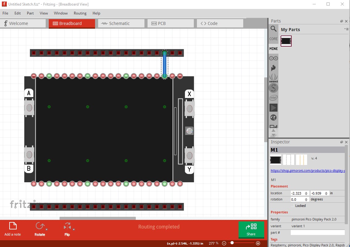
Not easily, I make parts because I like making parts (and am retired and thus can do what I like!) In any case here is the lcd part. It has some oddnesses though. In breadboard it has visible (but not physically present) pads on the edge of the board like this (you can see the pads that are connected in the middle of the LCD panel, which don’t appear until connected to something.)
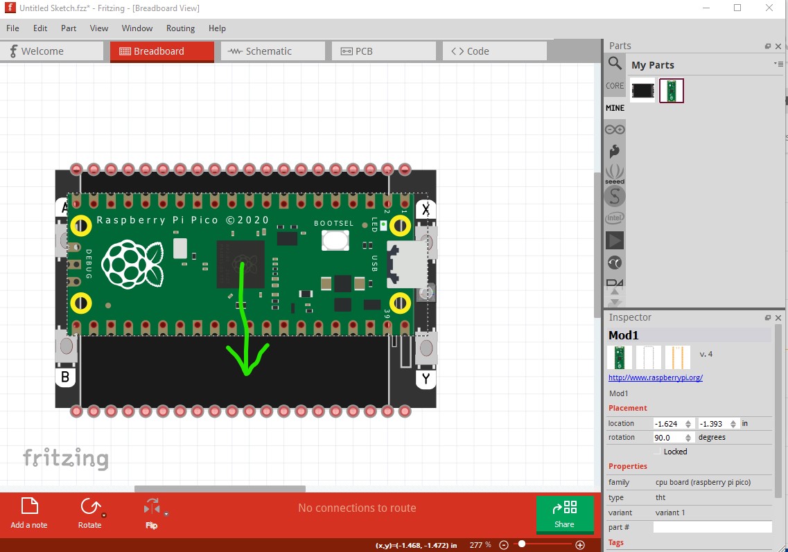
there are also pads in the correct place in the center of the lcd, but they don’t show up if not connected. That is so they will connect with the pico parts like this:
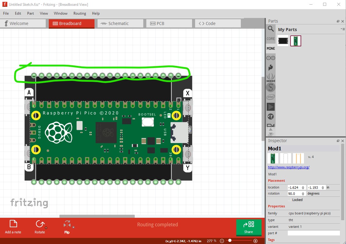
If I place the pico board a little above the rows of connectors then drag it down in the direction of the green arrow, the connectors will turn green (to indicate they have connected) like this:
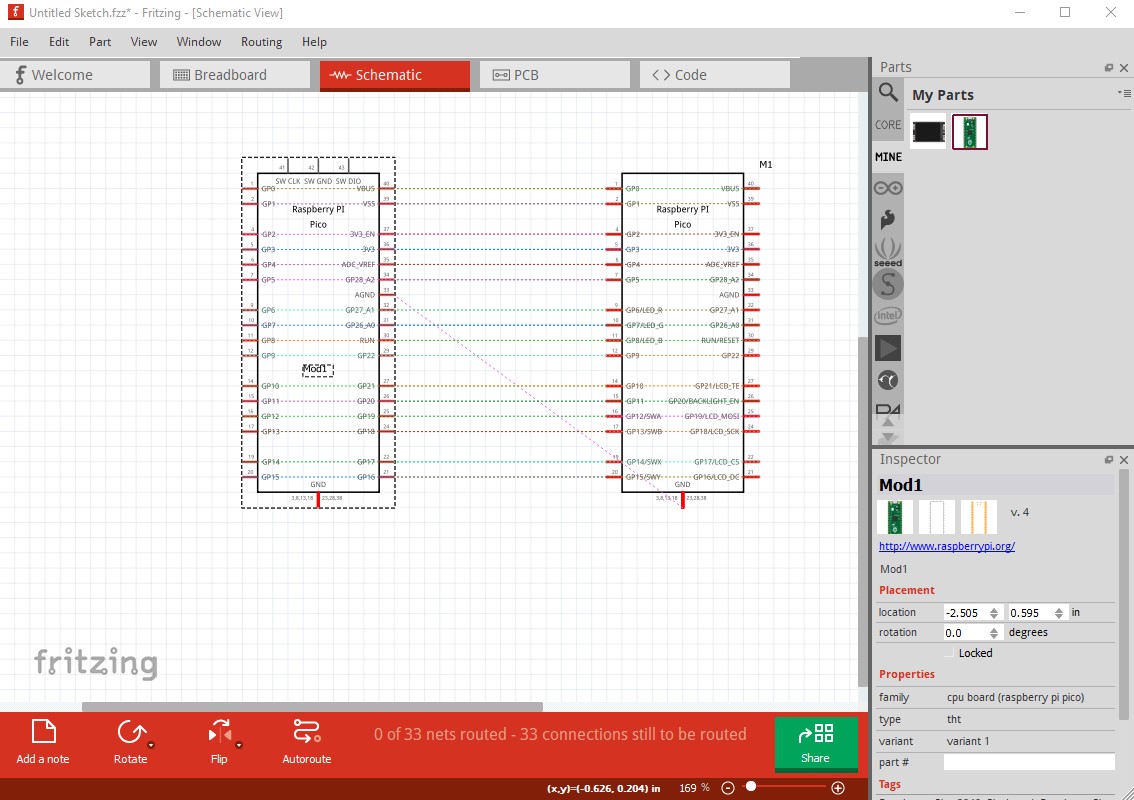
If I click on the pico and select move to the back it will disappear under the LCD to look like it would in real life. As a result of the connections in breadboard, in schematic the connections between the pico and the LCD are made
although it is a little messy. The pads on the outside allow you to make connections to the LCD pins in a visible manner if you aren’t using the LCD with a pico (or don’t want to put the pico under or on top of the lcd.) In that case wires from the edge pads will do the same thing. Here is the part.
pimoroni-Pico-Display-Pack-2.0.fzpz (14.6 KB)
Peter
Hey Peter,
If there is a charity I can donate to please let me know.
I am currently creating a device to help disabled people such as myself so the help you have provided will go a long way towards that.
All the best
Dave
I like the Salvation Army (but don`t know if they are only local here in Canada or not.
Peter
Hey Peter,
There is one 300 meters from ym house. I will pop a donation in tomorrow.
Thanks again
Dave