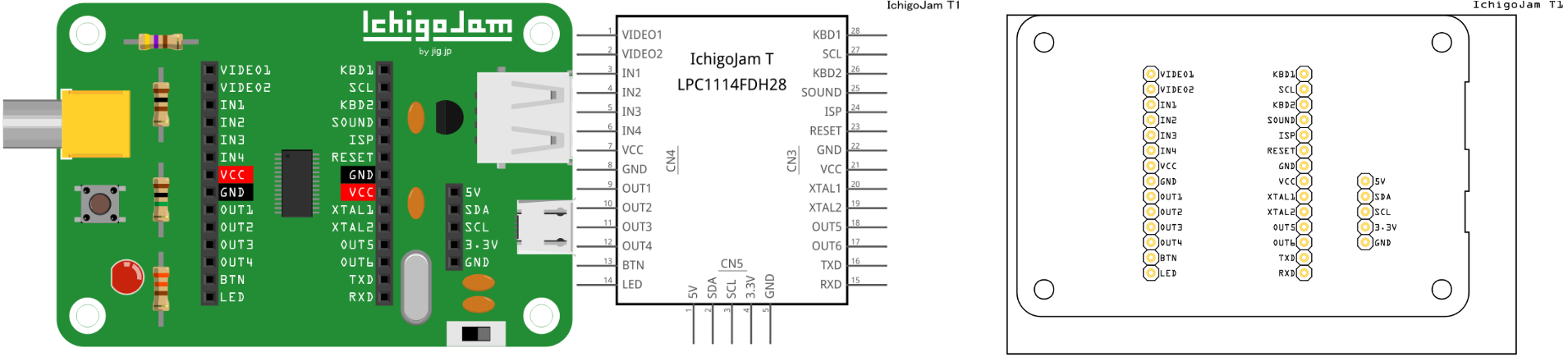
IchigoJam T (IchigoJam means also strawberry jam) is a low-power, low-cost single board computer development platform.
As “Kid’s PC”, it is developing for children’s programming education.
In this series, the BASIC language is activated just by turning on the power, and there is a feature that it can program immediately.
Because it has I/O ports, it is easy to control electronic work, not limited to programs.
IchigoJam is an educational computer comparable to ARDUINO and Raspberry Pi.
IchigoJam BASIC RPi1.2 https://ichigojam.github.io/RPi/
IchigoJam was created to make it easy to enjoy programming in the BASIC language.
It can also be used for electronics hobby by using functions such as digital I/O, PWM, I2C and UART.
There are some internal issues (mostly minor, left over from the clone from the rpi board). Is IN3 connected to SDA (the buses make it so which may or may not be correct)? Presumably all 3 gnd pins should be bused (only 2 are at present)? The two VCC pins are bused together but don’t go to either the 5V pin nor the 3.3V pin (but perhaps they are not supposed to?) The pins in the fzp file should be male not female (this doesn’t refer to the type of connector but rather female is for breadboard pins and male is usual for parts). If you supply the information about how the buses should connect I can clean the part up for you.
Is IN3 connected to SDA (the buses make it so which may or may not be correct)?
Yes, IN3 and SDA are shared bus.
Presumably all 3 gnd pins should be bused (only 2 are at present)?
You are correct. All three GND pins should be bused.
I fixed it on new fzp file.
The two VCC pins are bused together but don’t go to either the 5V pin nor the 3.3V pin (but perhaps they are not supposed to?)
Two VCC pins between CN3 and CN4 are connected inside CPU.
The VCC(CN3) and 3.3V(CN5) are connected on the board.
5V(CN5) is directly supplied from USB power supply and does not pass through the inside of CPU.
The pins in the fzp file should be male not female (this doesn’t refer to the type of connector but rather female is for breadboard pins and male is usual for parts).
I couldn’t understand it.
I checked pins of RPi3 and ARDUINO UNO by “new parts editor” of Fritzing.
On RPi3, all pins are set to male, but on ARDUINO all pins are set to female.
Therefore I think that all pins of IchigoJam T should be set to female.
If you supply the information about how the buses should connect I can clean the part up for you.
Thank you so much.
If new fzp file (ver.06DEC2017) is incorrect, fix it please.
Yep that looks to have fixed the bus issues. I did some more clean up though
fzp changes
global breadboardbreadboard to breadboard (as the svg layerId is breadboard) and if the layers don’t match the svg export function wion’t export the part.
remove terminalId from breadboard connector defs (they aren’t in the svg and not needed they are needed in the schematic definition though)
Bus defs in the fzp file cleaned up, and refer to pins that no longer exist and the ids are redundant without pins (not a problem, just messy and waste space). Renamed the bus ids to reflect what the bus is.
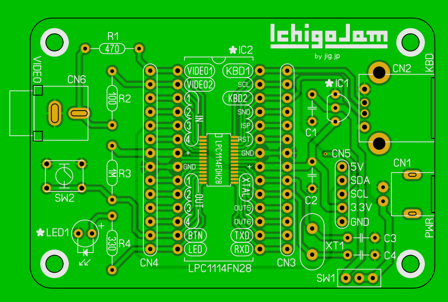
pcb svg
in pcb.svg reversed groups copper0/copper1 to be copper1/copper0 (as that is the order for smd parts)
Increased the hole size from 0.028in to .038 for .1 square pins.
Converted silks screen from white to black so it shows in Inkscape.
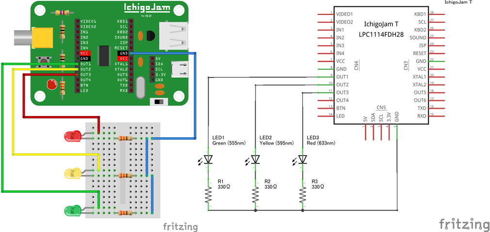
Then I created a new part and changed the pin type from female to male so you can see the difference (either will work, but there are cosmetic differences between the two). The female type on parts is usually for a pin that would overlap if you placed the part on the breadboard (a female pin won’t connect to the breadboard if it is on top of it, a male pin will). Then I created the sketch below with both parts in a typical test setup to verify everything is OK. The two parts will be in the temp parts bin and can be exported to get you the individual parts to see what changes I have made.
Thank you very much for your cleaning up.
I tried to understand the layer rules of parts design, but it was so difficult for me.
Although I referred Fritzing graphic standards when creating the parts of IchigoJam T, couldn’t find the layer naming rules, so didn’t understand reason why the word “breadboard” repeats 3 times.
Also, I cannot completely understand the difference the gender of pins, but found that behavior differs when overwrapping breadboard and pins.
Finally, exported new data from your file is as follows.
But schematic image sometimes rotates clockwise 90 degrees.
What is the reason for this?
No problem, it’s in all our interests to encourage people to make new parts and you are already doing a good job. As noted below so far a lot of the stuff isn’t documented and gets passed on here in the forums (we really should get to documenting it sometime but haven’t yet).
That’s because the rules are secret (or at least not documented.) The layerId in the fzp file needs to match that in the svg and is usually breadboard. The breadboardbreadboard is a special layer id that identifies the breadboards. Internally the code deals differently with some parts of things if other code words are also present (the module id in the fzp is one and I think family is another). As a result you sometimes see it in other parts although in anything other than a breadboard it isn’t needed. The problem in this case was that it didn’t match the layerId in the svg and that causes the svg export to screw up. I could have changed the svg to breadboardbreadboard and that would have worked fine as well.
I’m not sure I completely understand it either but the main use for female is the pins in the breadboard (which are all female). They will accept parts and wires (both of which have male pins). I think the rule is a connection can only be male pin to female pin so male won’t connect to male and female won’t connect to female. In parts such as your board all male pins is the normal case. The exception is in parts like the arduino nano that have pins that will fit in the breadboard horizontally and as well some pins vertically which will connect to the breadboard but would be shorted by the vertical connection of the breadboard pins. In that case the vertical pins are set to female so they will not auto connect to the breadboard. Because this is confusing some parts in core use female connectors where they don’t need to which spreads the confusion along as we clone parts in core and copy them. Eventually I hope to be able to get to a clean up of the parts in core (there are a number of errors in various parts) via a parts checking script I’ve been working on for the last year or so. Its close but still has bugs (and probably always will ).
This one is a bug in Fritzing. Its on my list to try and fix when I finish the parts script, along with its friend which misaligns the part on the grid when you rotate it until you move the part when it snaps to the grid correctly. There are (again secret) parameters that you can add to the fzp file to specify orientation but I don’t think they fix this problem, I think it is actually a bug in the code some bit of state gets set at random (or more probably isn’t set to a correct value) to cause the rotation, but finding it is likely to be exciting.
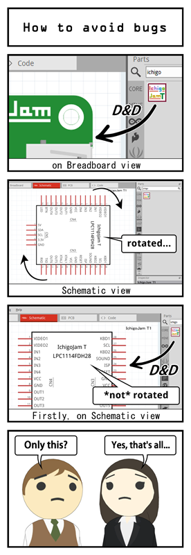
With your support the new part of IchigoJam T was completed.
The bug with which the schematic image rotates could be avoided by devising the Fritzing operation.
I thank you once again.
So IchigoJam T may grow to an educational one-board PC comparable to Arduino or RPi3, this new part should be added to the main library in Fritzing. Is it possible?
This is actually the one part of Fritzing that gets updated often. You can create a pull request on the Fritzing-parts Github page and the next time they do an update hopefully they will include your part.
As you can see it was last updated on Oct 19 and since Fritzing just checks the repo it would have updated around the same time. It may just be that they are small updates that happen quickly and you didn’t notice or maybe it hasn’t checked since then.
You may want to click the help->check for updates buttong. While this should happen on every startup, I have found that sometimes I have to click the button to get an update.
If you have found a solution to this I’d like to hear it, as nothing I know of actually seems to work. There are undocumented (but used sometimes) orientation commands in the fzp file, but even they don’t seem to stop the part from being rotated sometimes on insertion.
I have just created a new pullrequest of IchigoJam T now and hope this will be added to the Core Parts in Fritzing.
Please judge whether this part is appropriate.
I should also say I am not the maintainer. The maintainer is very active and even merged a change to the gh-pages branch only 5 hours ago so once you make the request it should not take long to get it merged. You may want to include a link to this thread so they can see the work that has gone into it.
Edit: Looks like you made the request in the Sparkfun repo https://github.com/sparkfun/Fritzing_Parts/pulls . I think you should close that and move it to the Fritzing parts repo I linked to earlier. The sparkfun is for sparkfun brand parts.
It’s my mistake.
I have just closed a pull request in sparkfun/Fritzing_Parts and recreated in fritzing/fritzing-parts.
Thank you so much for correcting my mistake!
Interesting! Thank you, that may provide a clue to what is happening. It looks like something in breadboard is affecting the rotation in schematic, when dragged in to schematic directly works properly. If I can figure out what is being affected in the source it can perhaps be fixed. I’d never thought to try dragging the part in to schematic (and may not have noticed it always seems to work properly when dragged in to schematic.) In a test dragging 8 copies in to schematic are all aligned correctly. Closing and restarting Fritzing and dragging 8 copies in to breadboard gets 6 correct and 2 rotated in schematic. So a work around until we get it fixed is to drag your parts in to schematic first.