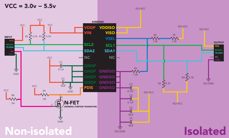
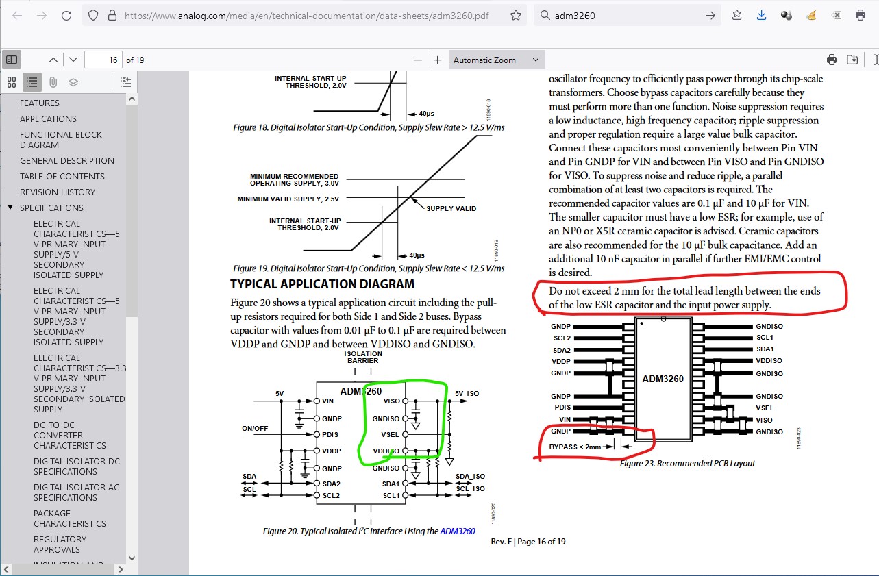
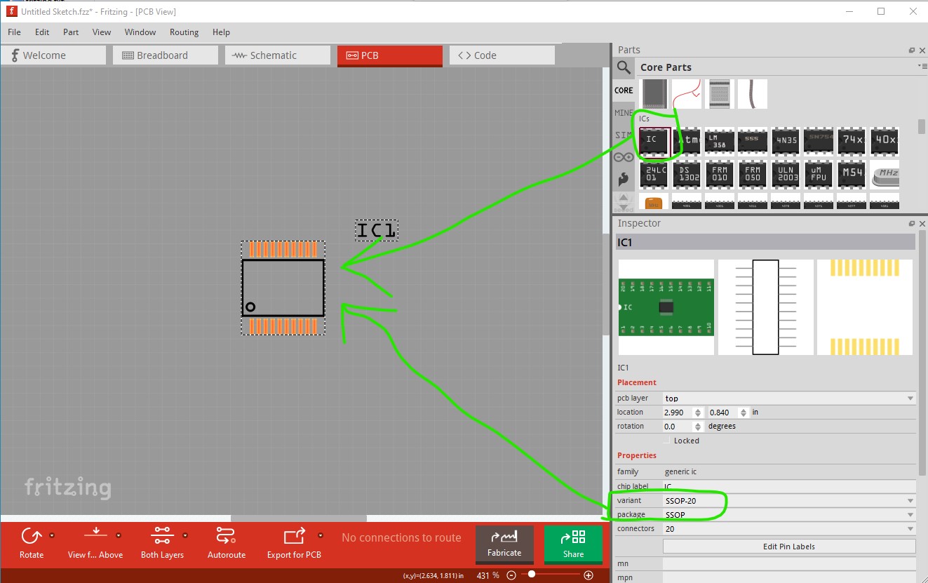
Note in pcb they want low ESR capacitors within 2mm of the IC pins on the various power supplies. I would use the identical pcb layout as shown in the data sheet (circled in red in the above diagram.) Your first problem is that there doesn’t appear to be a Fritzing part for the adm3260 so you need to make one using the generic IC.
drag the generic IC (which will be 8 pin DIP by default) in to the sketch then in Inspector (the lower right window) set the variant to ssop-20 and the connectors to 20 and the package to SSOP so pcb is correct. Then switch to schematic
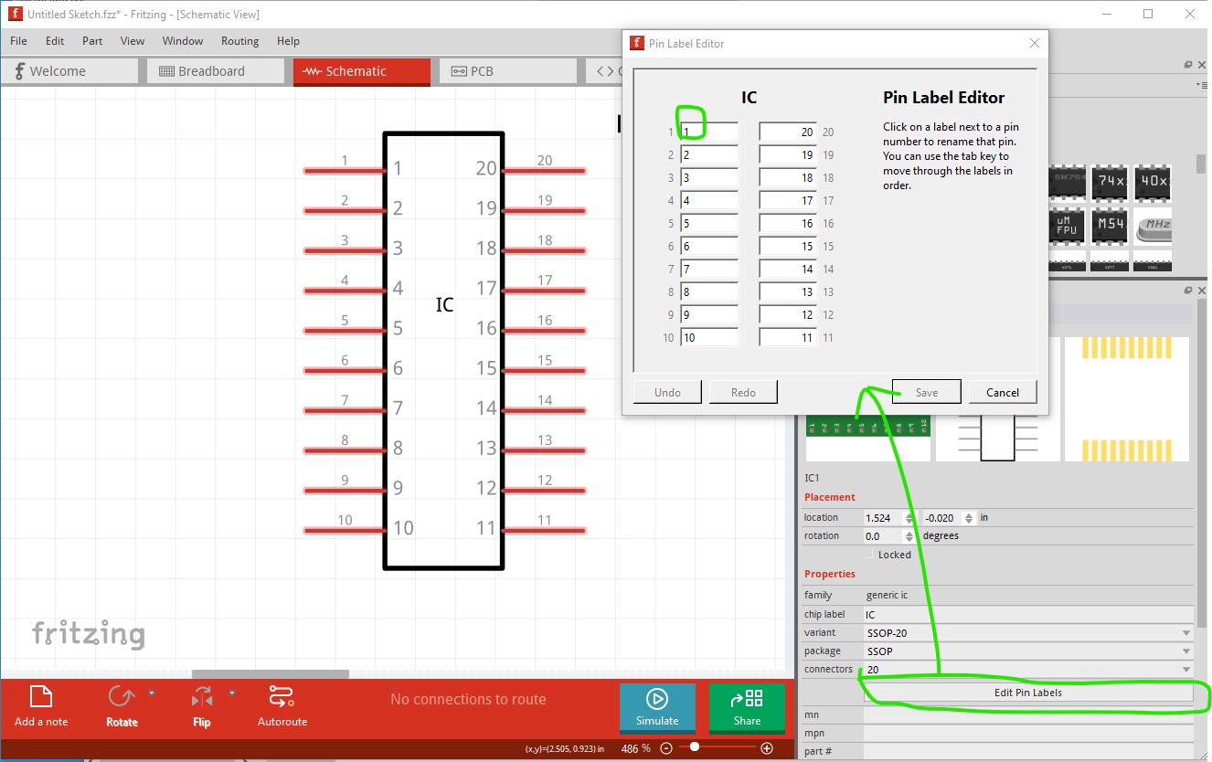
and click on edit pin labels. Then type in the name of each of the pins in the text box (or leave them as the default which is the pin numbers.) Now you have the ADM 3260 part and you can create and route the schematic which will reflect the connections in to pcb view. They you can switch to pcb view and route the board (you will need to add the necessary other components such as SMD resistors and capacitors as well but they should all be in core parts.)