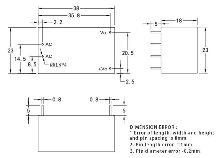
This should do what you want. As always before ordering boards, print out the pcb footprint at 1:1 scale and compare it to a real part (as I don’t have one only the data sheet!)
HLK-5M05.fzpz (6.8 KB)
Peter
i can’t believe you put that graphic on the breadboard image. now that’s dedication. somebody buy this man a beer, lol.
I can’t take credit for that one, it was in the original part by someone else, I just modified it.
Peter
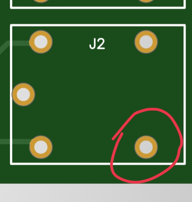
Hello, I have a problem, the holes are too small
I want to increase the thickness of the holes
AC , + , -
Like relay holes in photo .
I’m plz help me, thanks
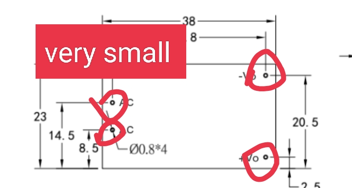
The holes in the part above are 0.9652mm (0.038in, the size for a 0.1in header) so should be correct for a 0.8mm pin. Why do you think they are too small? is the above data sheet incorrect and the pins are not 0.8mm (and if so what is their size?)
Peter
When placed, it is difficult to enter
this holes is good lock img
hole dimater 1.4
ring thickness 0.8

A 1.4mm (0.056in) hole seems fairly large for a 0.8mm pin. The data sheet here:
doesn’t give a recommended hole size for the pcb, but does indicate the pin is 0.8mm diameter. If the hole is too large you may have stability problems. In any case here is a part with 0.56in holes.
HLK-5M05-1_4mm-pin.fzpz (6.9 KB)
Peter
I had a batch of HLK-5Ms delivered instead of HLK-01s and the seller is playing dead. On a second test order I got even more and are thinking of using them now (particularly for boards with featuritis ![]() ). So I found this thread.
). So I found this thread.
Being curious I had a measure and none of those pins is actually 0.8mm. They may have used raw wire of 0.8mm before coating. But all pins measure between 0.9mm and 1.0mm.
This would make the original design a very snug fit indeed.
Then perhaps the 1.4mm part just above is indeed correct. I don’t have any parts and can thus only go from the data sheet.
Peter