Hi everyone,
I’m working on a PCB design that will include two DC‑DC converter modules from TRACO Power and I need some help with the PCB footprints.
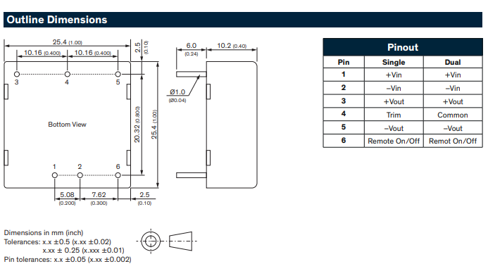
1) TRACO Power THL30WI
I have the datasheet here: https://www.tracopower.com/thl30wi‑datasheet
This is a 30 W isolated DC‑DC converter in a through‑hole package (6 pins). The datasheet shows overall dimensions and pin positions.
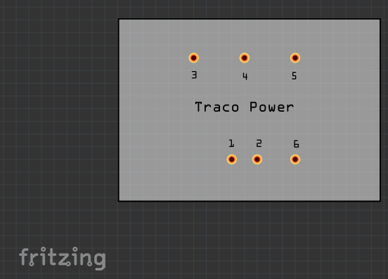
If you just want the foodprint for the PCB, and don’t need breadboard illustrations, and only use it once or twice in you sketch, you could just directly set the THT holes in your PCB.
Use vias (scoll to the PCB section of the core parts) and set a matching diameter and ring size. Like so:
Yes, I had considered implementing it that way. However, I still need the schematic diagram for my design, and unfortunately I don’t have experience creating component footprints yet. Any guidance would be greatly appreciated.